Power transmission cable bending device control system

A device control and cable technology, applied in the direction of equipment for connecting/terminating cables, etc., can solve problems such as high requirements for shape accuracy and complex requirements, and achieve the effect of saving equipment space, simplifying equipment structure, and ensuring shape accuracy

Active Publication Date: 2015-07-29
NANTONG FREE MECHANTRONIC CO LTD
View PDF4 Cites 0 Cited by
  • Summary
  • Abstract
  • Description
  • Claims
  • Application Information

AI Technical Summary

Problems solved by technology

Sometimes, the requirements for this shape are more complex, and the shape accuracy requirements are higher

Method used


Image

  • Power transmission cable bending device control system
  • Power transmission cable bending device control system
  • Power transmission cable bending device control system

Examples


Embodiment Construction

[0014] Combine below Figure 1-4 The present invention will be described in detail.

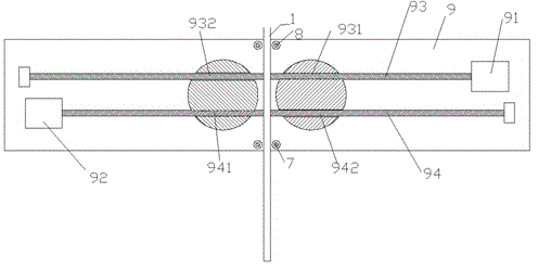
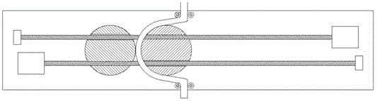
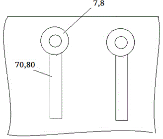
[0015] According to an embodiment, a control system for bending equipment of a cable for power transmission in the present invention includes a DSP controller, a motor drive circuit, and a bending equipment; the bending equipment includes a frame 9 and a left sliding forming die and a right sliding Forming dies, the two forming dies are cylindrical, which can be driven to slide on the frame, and upper guide roller pairs 8 and lower guide rollers are respectively provided at the middle positions of the upper edge and the lower edge of the frame 9. The pair of rollers 7, the spacing between the two rollers of the upper guiding roller pair 8 and the spacing between the two rollers of the lower guiding roller pair 7 are aligned with each other for the cables 1 to pass through. The top of frame 9 is provided with the first screw rod 93 that extends left and right direction, and the right end of f...


PUM


Abstract

A power transmission cable bending device control system comprises a DSP controller, a motor drive circuit and a bending device. The bending device comprises a frame (9) and left and right slide forming dies which are arranged transversely; the middle of the upper and lower edges of the frame (9) are provided with an upper guide roller pair (8) and a lower guide roller pair (7), and a cable (1) is allowed to penetrate the spacing between two rollers of the upper guide roller pair (8) and the spacing between two rollers of the lower guide roller pair (7).

Description

technical field [0001] The invention relates to the construction treatment of cables for power transmission, in particular to a control system for bending equipment of cables for power transmission. Background technique [0002] In the process of construction and application of power transmission cables, it is often necessary to bend the wiring head to adapt to the shape of the specific fixed part of the power equipment, so as to securely connect the cables. Sometimes, the requirements for this shape are more complex, and the shape accuracy is higher. Therefore, a power-controlled forming device is needed to quickly and accurately bend and shape the cable head. Contents of the invention [0003] The object of the present invention is to provide a bending equipment control system for electric power transmission cables, which can satisfy the above-mentioned requirements. [0004] According to the present invention, a bending equipment control system for electric power tran...

Claims


Application Information

Patent Timeline
Patent Type & Authority Applications(China)
IPC IPC(8): H02G1/14
Inventor 楼国华
Owner NANTONG FREE MECHANTRONIC CO LTD
Why Eureka
Try Eureka