Steering device
一种转向装置、转向轴的技术,应用在转向柱、装在车上的转向控制、运输和包装等方向,能够解决锁定功能受损、无法转向、转向锁定机构破损等问题
- Summary
- Abstract
- Description
- Claims
- Application Information
AI Technical Summary
Problems solved by technology
Method used
Image
Examples
no. 1 Embodiment approach
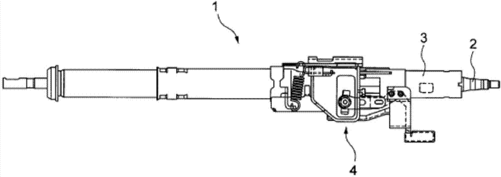
[0066] refer to Figure 1 to Figure 6B A first embodiment of the present invention will be described. figure 1 It is a side view showing the steering device 1 according to the first embodiment of the present application.
[0067] Steering device 1 mainly comprises: will be installed on vehicle rear side (towards figure 1 is the right side) the steering wheel (not shown) is rotated toward the front side of the vehicle (towards figure 1 Steering shaft 2 that transmits to the left side); steering column 3 that pivotally supports the steering shaft 2; and position adjustment that fixes the vehicle rear side portion of the steering device 1 to the vehicle body and enables tilt position adjustment and telescopic position adjustment Institution 4.
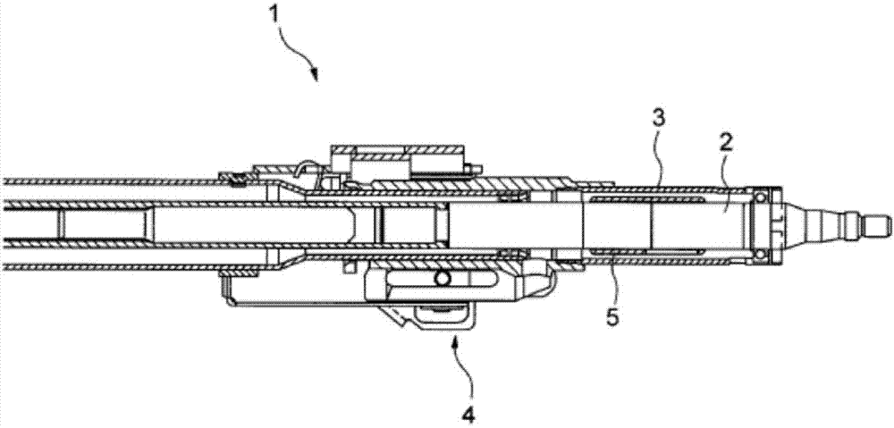
[0068] figure 2 It is an enlarged cross-sectional view of the vicinity of the position adjustment mechanism 4 of the steering device 1 according to the first embodiment of the present application.
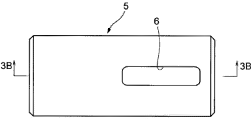
[0069] A key lock boss 5 constitu...
no. 2 Embodiment approach
[0091] Next, while referring to Figure 8 as well as Figure 9A , Figure 9B A steering device according to a second embodiment of the present application will be described. The steering device according to the second embodiment differs from the steering device 1 according to the first embodiment only in the shape of the steering shaft and the shape of the slip ring, and the other configurations are the same as those of the first embodiment. Therefore, in the description of the second embodiment, only the shapes of the steering shaft and the slip ring will be described, and the description of other configurations will be omitted.
[0092] Figure 8 It is a figure which shows the cross section of the side surface of the steering shaft 20, the key lock boss|hub 21, and the slip ring 22 of the steering apparatus concerning 2nd Embodiment of this application.
[0093] In the second embodiment, a reduced-diameter portion 23 that is smaller in diameter than other adjacent portio...
no. 3 Embodiment approach
[0099] refer to Figure 10A , Figure 10B A third embodiment of the present application will be described. Figure 10A shows the side surface of the steering shaft 30 according to the third embodiment of the present application, Figure 10B The side surface of the steering shaft 30 according to the third embodiment of the present application, the slip ring 32 fitted on the steering shaft 30 and the cross section of the key lock boss 31 are shown.
[0100] The steering device according to the third embodiment of the present application differs from the steering device according to the first embodiment only in the shape of the steering shaft 30 , and the other configurations are the same as those of the first embodiment. Therefore, in the description of the third embodiment, only the shape of the steering shaft 30 will be described, and the description of other configurations will be omitted.
[0101] Such as Figure 10A As shown, in the steering shaft 30 according to the th...
PUM
 Abstract
Description
Claims
Application Information
 - R&D
- Intellectual Property
- Life Sciences
- Materials
- Tech Scout
- Unparalleled Data Quality
- Higher Quality Content
- 60% Fewer Hallucinations
Browse by: Latest US Patents, China's latest patents, Technical Efficacy Thesaurus, Application Domain, Technology Topic, Popular Technical Reports.
© 2025 PatSnap. All rights reserved.Legal|Privacy policy|Modern Slavery Act Transparency Statement|Sitemap|About US| Contact US: help@patsnap.com


