Permanent magnetic mechanism capable of adjusting switching on-off time and adjusting method thereof
What is AI technical title?
AI technical title is built by Patsnap AI team. It summarizes the technical point description of the patent document.
A permanent magnet mechanism, closing and opening technology, which is applied in the direction of protection switch operation/release mechanism, calibration/finding protection device, etc., to achieve good adaptability, ensure quick action, and reduce the effect of protection opening time
Inactive Publication Date: 2015-08-05
深圳市安正顺电气科技有限公司
View PDF5 Cites 1 Cited by
Summary
Abstract
Description
Claims
Application Information
AI Technical Summary
This helps you quickly interpret patents by identifying the three key elements:
Problems solved by technology
Method used
Benefits of technology
Problems solved by technology
This method can change the closing and opening time within a certain range and realize the synchronism of the circuit breaker, but it has certain limitations.
Method used
Image
Click on the blue label to locate the original text in one second.
Reading with bidirectional positioning of images and text.
Examples
Embodiment
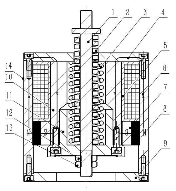
[0028] This embodiment includes: a permanent magnet mechanism 14 and an outer yoke 6 arranged inside the permanent magnet mechanism 14, an upper yoke 4, a lower yoke 9, a moving iron core 10, an iron core back cover 11, a pull rod 1, and a switch spring 3. Contact spring 2, adjustment nut 12, lock nut 13, inner yoke 7, coil 5, permanent magnet 8; outer yoke 6, upper yoke 4 and lower yoke 9 are arranged on the outside of permanent magnet mechanism 14 The upper and lower ends of the outer yoke 6 are respectively fixedly installed, and the three form an unclosed cavity. The upper yoke 4 is provided with a circular steel pipe, and the inner wall is provided with a stepped circle. The moving iron core 10 is located at the outer yoke 6, In the cavity formed by the upper yoke 4 and the lower yoke 9, the iron core back cover 11 is arranged at the lower end of the moving iron core 10, and the opening spring 3 is placed in the cavity formed by the moving iron core 10, the iron core back ...
PUM
Abstract
The invention belongs to the technical field of electrical switches, and relates to a permanent magnetic mechanism capable of adjusting the switching on-off time and an adjusting method thereof. The permanent magnetic mechanism comprises a permanent magnetic mechanism, and an outer yoke, an upper yoke, a lower yoke, a moving core, a core back cover, a pull rod, a switching-off spring, a contact spring, an adjusting nut, a locking nut, an inner yoke, a coil, and a permanent magnet, all of which are arranged inside the permanent magnetic mechanism. The outer yoke is arranged at the outer side of the permanent magnetic mechanism, the upper yoke and the lower yoke are fixedly installed at the upper and lower ends of the outer yoke, the switching-off spring is arranged in a cavity formed by the moving core, the core back cover and the upper yoke, and the contact spring is arranged between the lower end of a stepped circle at the upper end of the pull rod and the core back cover. By adopting the permanent magnetic mechanism of the invention, the switching on-off time can be adjusted, the time of tripping protection can be effectively shortened, and the quickness of line quick-break protection is ensured. The permanent magnetic mechanism and the adjusting method are especially suitable for a circuit break of which both the switching-off spring and the contact spring participate in the switching-on / off process and which is equipped with multiple permanent magnetic mechanisms, and are applicable to the field of electric power.
Description
technical field [0001] The invention belongs to the technical field of electrical switches, and is particularly designed to a permanent magnet mechanism capable of adjusting closing and opening time. Background technique [0002] In the field of intelligent distribution network, fast protection circuit breakers are widely used. The reason is that the distribution network line can be segmented and demarcated, and the power failure range can be controlled to a minimum by relying on the coordination of protection time steps in the event of a fault. The faulty circuit breaker can quickly isolate the faulty area, shorten the fault finding time, reduce the power failure radius, and quickly restore the normal power supply in the non-faulty area. It is of great significance to build a self-healing automation system network. However, all of this depends on the accurate judgment of the circuit breaker protection system and the reliable snap-action performance of the circuit breake...
Claims
Application Information
Patent Timeline
Application Date:The date an application was filed.
Publication Date:The date a patent or application was officially published.
First Publication Date:The earliest publication date of a patent with the same application number.
Issue Date:Publication date of the patent grant document.
PCT Entry Date:The Entry date of PCT National Phase.
Estimated Expiry Date:The statutory expiry date of a patent right according to the Patent Law, and it is the longest term of protection that the patent right can achieve without the termination of the patent right due to other reasons(Term extension factor has been taken into account ).
Invalid Date:Actual expiry date is based on effective date or publication date of legal transaction data of invalid patent.

