
A three-position operating device for a load switch

A technology of operating device and load switch, which is applied in the field of ring main unit, can solve the problems of large volume, difficult assembly and complex structure of the three-station operating mechanism, and achieve the effect of novel structure, less transmission links and small volume

Active Publication Date: 2022-06-28
COOPER EDISON PINGDINGSHAN ELECTRONICS TECH
View PDF0 Cites 0 Cited by
  • Summary
  • Abstract
  • Description
  • Claims
  • Application Information

AI Technical Summary

Problems solved by technology

At present, the three-station operating mechanism used in RVAC series products is large in size, complex in structure, with many parts, difficult to assemble, and high in cost.

Method used


Image

  • A three-position operating device for a load switch
  • A three-position operating device for a load switch
  • A three-position operating device for a load switch

Examples


Embodiment Construction

[0031] Specific examples are given below to further describe the technical solution of the present invention in a clear, complete and detailed manner. This embodiment is the best embodiment on the premise of the technical solution of the present invention, but the protection scope of the present invention is not limited to the following embodiments.

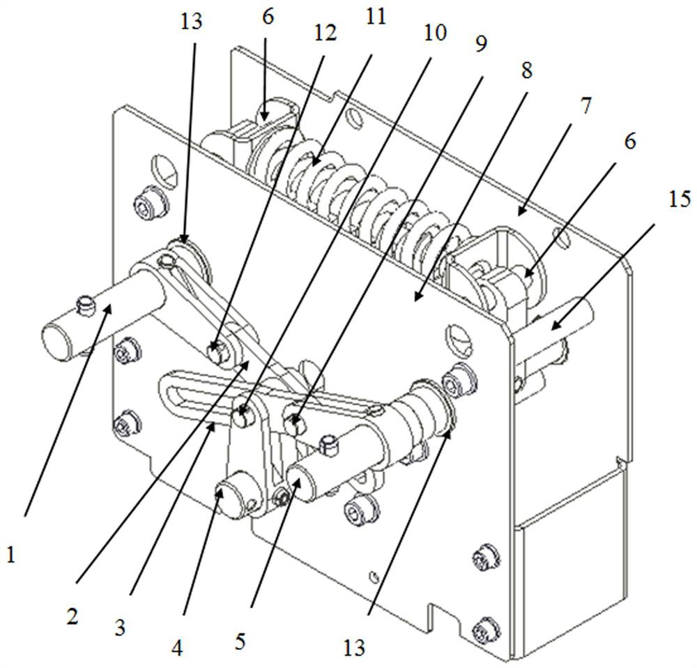
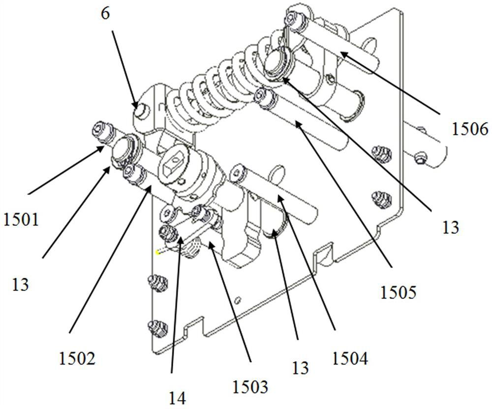
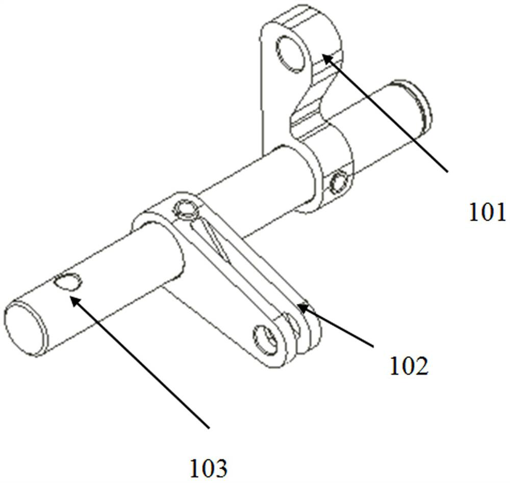
[0032] A three-position operating device for a load switch, comprising a first side plate 7 and a second side plate 8 arranged oppositely and in parallel, and also includes a connecting operation shaft 1, a grounding operation shaft 5, an output shaft 4, a first transmission coupling Rod 2, second transmission connecting rod 3, spring assembly 11, limit shaft 15, isolation limit device 14, the connection operation shaft 1, output shaft 4, grounding operation shaft 5, and limit shaft 15 are arranged in sequence Between the side plate 7 and the second side plate 8, the connecting operation shaft 1, the output shaft 4, and the groun...


PUM


Abstract

A three-position operating device for a load switch, comprising a first side plate and a second side plate arranged oppositely and in parallel, and also includes a connecting operation shaft, a grounding operation shaft, an output shaft, a first transmission link, a second transmission Connecting rod, spring assembly, limit shaft, isolation limit device, the connection operation shaft and the ground operation shaft are symmetrically arranged left and right, and the two and the output shaft are arranged in an inverted triangle, and the spring assembly is located between the connection operation shaft and the ground operation shaft. Between and through the first pin shaft pin connection, the isolation limit device is set in contact with the output shaft, the connection operation shaft and the output shaft are connected through the first transmission connecting rod, and the grounding operation shaft and the output shaft are connected through the second transmission connection rod , both the first transmission link and the second transmission link are provided with long circular grooves to realize the free conversion and effective limit of the output shaft among the three positions of connection, isolation and grounding, and the storage of the long circular groove and the spring assembly The process of energy and energy release is coordinated; the structure is novel, the operation is efficient, and the transmission links are few.

Description

technical field [0001] The invention relates to the technical field of ring network cabinets, and relates to a three-station operating device for a ring network cabinet, in particular to a three-station operating device for a bidirectional quick-acting load switch with fast breaking and closing capabilities. Background technique [0002] The ring network cabinet is a group of transmission and distribution electrical equipment installed in a metal or non-metal insulated cabinet or made into an assembled interval ring network power supply unit. It is used as the main equipment for the protection and segmental isolation of the cable distribution network. Safe and reliable performance, compact and beautiful appearance are widely used in urban power grids. [0003] At present, with the rapid development of the national grid, the application of miniaturized and compact ring network cabinets has been widely used. The ring main unit usually has three stations of closing, opening an...

Claims


Application Information

Patent Timeline
Patent Type & Authority Patents(China)
IPC IPC(8): H01H3/02
CPCH01H3/02
Inventor 王成祎朱治才陈军
Owner COOPER EDISON PINGDINGSHAN ELECTRONICS TECH
Learn More