Perspective ruler and realization method thereof

An implementation method and a ruler technology, applied in the field of hand-painting tools, can solve problems such as time-consuming, increasing the time and complexity of hand-painted painting, and difficulty in mastering perspective.

Inactive Publication Date: 2015-08-12
SICHUAN NORMAL UNIVERSITY
View PDF3 Cites 2 Cited by
  • Summary
  • Abstract
  • Description
  • Claims
  • Application Information

AI Technical Summary

Problems solved by technology

[0002] For many beginner painters, perspective is the most difficult and time-consuming skill to master. In the preliminary investigation, we found that many beginners encountered difficulties in learning the course of perspective, so they had a feeling for painti

Method used


Image

  • Perspective ruler and realization method thereof
  • Perspective ruler and realization method thereof
  • Perspective ruler and realization method thereof

Examples


Embodiment 1

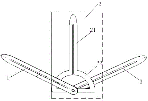
[0028] like figure 1 As shown, the present embodiment provides a perspective ruler, which mainly includes a first ruler 1, a second ruler 2 and a third ruler 3, the tail ends of the three rulers are connected to each other by rotation, and the thickness is 1.5mm, and the three rulers All can rotate arbitrarily along a plane, that is, the first ruler 1, the second ruler 2 and the third ruler 3 are plane rotations; further, the second ruler 2 is located between the first ruler 1 and the third ruler 3, based on the above, The rotation planes of the first ruler 1 , the second ruler 2 and the third ruler 3 are parallel to each other.

[0029] The first ruler and the third ruler are rulers with scales on the ruler. Further, a hole is provided along the length direction of the ruler. The tail end of the first ruler and the third ruler is its one end. 4mm screw nut connection. The second ruler is made up of coaxial ruler part 21 and protractor part 22, wherein, ruler part 21 is prov...

Embodiment 2

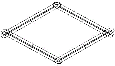
[0038] like figure 2 As shown, the difference between this embodiment and Embodiment 1 is that the perspective ruler in this embodiment is composed of four rulers, and the four rulers are connected end to end to form a quadrilateral, and the four corners of the quadrilateral are connection points, and the four rulers are connected end to end to form a quadrilateral. The ruler can be rotated around the corresponding connection points. Among them, the two diagonal connection points are connected with 4mm screw nuts and can be rotated, but cannot move; the other two diagonal connection points are connected with 2mm screw nuts, which can be rotated It can also be moved to facilitate the adjustment of the lengths of each side of the quadrilateral, and there is a standard millimeter scale on it. There are various and mature structures to realize this connection method, so I will not repeat them here. This perspective ruler is mainly used to draw circular and elliptical objects; fro...


PUM


Abstract

The invention discloses a perspective ruler and a realization method thereof. With the ruler and the realization method thereof, a problem that no professional drawing tool for perspective drawing is provided in the prior art can be solved. The perspective ruler comprises a first ruler, a second ruler, and a third ruler, wherein the tail ends of the three rulers are mutually connected in a rotation mode; the first ruler and the third ruler are straight ones; and the second ruler is formed by a straight ruler part and a protractor part, wherein the two parts are in a coaxial mode. The protractor part is a semi-circular protractor; the straight ruler part is connected with an arc end of the protractor part; and the bottom of the protractor part serves as the tail end of the second ruler and is a straight edge. The tail ends of the first ruler and the third ruler are connected with the center point of the straight edge of the protractor part in a rotation mode. According to the invention, a basic perspective angle of a product is determined according to the visual horizon location of the product; three corresponding perspective lines are found by using a perspective point of the product as a base point; a perspective relation of the product is found by means of a measurement comparison method; and a basic perspective relation of the product is drawn on a piece of paper based on a measured perspective angle, thereby determining the basic perspective information of the product.

Description

technical field [0001] The invention relates to a hand-drawing tool, in particular to a perspective ruler and a realization method thereof. Background technique [0002] For many beginner painters, perspective is the most difficult and time-consuming skill to master. In the preliminary investigation, we found that many beginners encountered difficulties in learning the course of perspective, so they had a feeling for painting Feelings of rejection and fear. However, in the prior art, there is no drawing tool for drawing perspective, and hand-painters often spend a lot of time practicing and painting the texture part of the product, which greatly increases the time and complexity of hand-painting. Contents of the invention [0003] The object of the present invention is to overcome the above defects and provide a see-through ruler with simple structure and convenient realization. [0004] In order to achieve the above object, the technical scheme adopted in the present in...

Claims


Application Information

Patent Timeline
IPC IPC(8): B43L13/00
CPCB43L13/144
Inventor 岑华余纯利罗云浩黄婷刘森林黄燕
Owner SICHUAN NORMAL UNIVERSITY
Why Eureka
Try Eureka