A lock cylinder with a limit post

A technology of limit posts and lock cylinders, which is applied to locks with rotating keys, construction locks, cylinder pin locks, etc., can solve the problems of poor anti-theft performance, high cost, and unsuitability for popularization and use of A-level anti-theft locks. The production cost is low, the effect of improving the anti-theft level and avoiding financial loss

Active Publication Date: 2017-04-26
杨振勇
View PDF10 Cites 0 Cited by
  • Summary
  • Abstract
  • Description
  • Claims
  • Application Information

AI Technical Summary

Problems solved by technology

[0003] In order to solve the problem that the existing A-level anti-theft locks have poor anti-theft performance, while the B-level anti-theft locks are relatively expensive and are not suitable for popularization and use, the present invention further proposes a lock cylinder with a limit post

Method used


Image

  • A lock cylinder with a limit post
  • A lock cylinder with a limit post

Examples


specific Embodiment approach 1

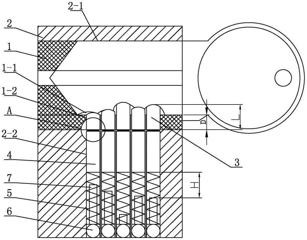
[0007] Specific implementation mode one: combine figure 1 and figure 2 Describe this embodiment, a lock cylinder with a limit post described in this embodiment includes an inner lock cylinder 1 and an outer lock cylinder 2, and the inner lock cylinder 1 is inserted into the jack 2-1 on the upper part of the outer lock cylinder 2. The embodiment also includes a plurality of upper cylinders 3, a plurality of lower cylinders 4, a plurality of springs 5, a plurality of sealing beads 6 and a plurality of limit posts 7, and the lower hole wall of the keyhole 1-1 of the inner lock core 1 A plurality of first through holes 1-2 are arranged side by side from left to right on the top, and a plurality of second through holes 2-2 are arranged side by side from left to right on the lower hole wall of the socket 2-1 of the lock cylinder 2. , a plurality of first through holes 1-2 communicate with a plurality of second through holes 2-2 in one-to-one correspondence, each first through hole...

specific Embodiment approach 2

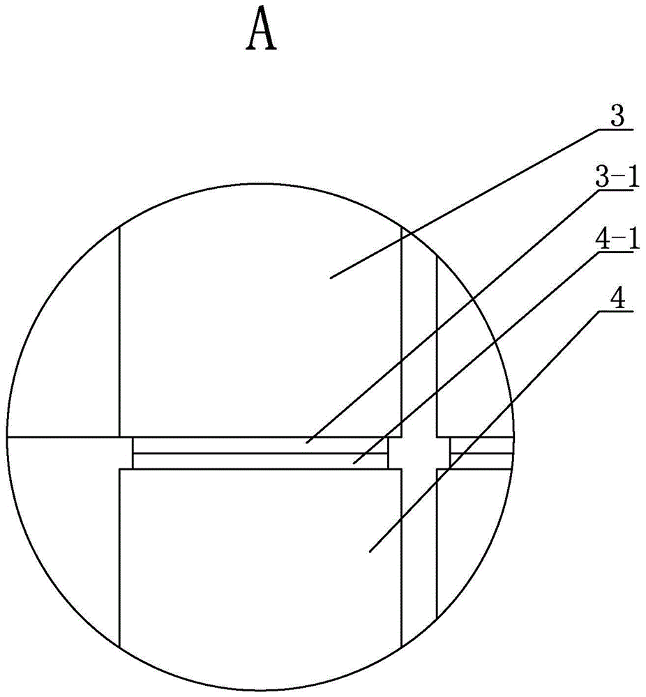
[0008] Specific implementation mode two: combination figure 1 and figure 2 To illustrate this embodiment, the lower end surface of each upper cylinder 3 of the lock core with a limit cylinder described in this embodiment is provided with a first boss 3-1, and the upper end surface of each lower cylinder 4 is provided with a The second bosses 4-1, each first boss 3-1 is in contact with a corresponding second boss 4-1.

[0009] The technical effect of this embodiment is: so set up, when the thief picks the lock, there will be misalignment between the upper cylinder 3 and the lower cylinder 4, and they will be separated from each other. Misalignment, the first boss 3-1 and the second boss 4-1 are mutually locked, preventing the upper cylinder 3 from detaching from the first through hole 1-2, effectively preventing the thief from picking the lock successfully. Other components and connections are the same as those in the first embodiment.

specific Embodiment approach 3

[0010] Specific implementation mode three: combination figure 1 and figure 2 Describe this embodiment, each upper cylinder 3 of a lock core with a limit cylinder described in this embodiment is an upper cylinder 3 made of a magnet, and each lower cylinder 4 is a lower cylinder made of ferrous metal 4.

[0011] The technical effect of this embodiment is: such arrangement prevents the upper cylinder 3 from being separated from the lower cylinder 4 when the thief picks the lock by the pop-off method, and effectively improves the anti-theft level of the lock cylinder. Other components and connections are the same as those in the first embodiment.


PUM


Abstract

Provided is a lock cylinder with limited posts. The invention relates to a lock cylinder, particularly to a lock cylinder with limited posts. With the lock cylinder, problems that the A-level anti-theft lock has a poor burglary prevention performance and the B-level anti-theft lock with the high cost is not suitable for popularization and application can be solved. A plurality of first through hole are successively formed in a lower hole wall of a key hole of an inner lock cylinder from left to right side by side; a plurality of second through holes are successively formed in a lower hole wall of an insertion hole of an outer lock cylinder from left to right side by side; and the multiple first through holes and the multiple second through holes are connected in a one-to-one correspondence mode. An upper column body is arranged in each first through hole; a lower column body, a spring, and a sealing bead are successively arranged at each second through hole from top to bottom; and one limiting post is arranged in each spring. A distance H between an upper end surface of each limited post and a lower end surface of each corresponding lower column body is H; a depth of each first through hole is D; a height of each upper column body is L; and the L is larger than the H and the H is larger than the L minus D. The lock cylinder is used for burglary prevention.

Description

technical field [0001] The invention relates to a lock cylinder, in particular to a lock cylinder with a limit post, and belongs to the field of mechanical locks. Background technique [0002] The level of my country's anti-theft locks is divided into two types: ordinary protection level and advanced protection level, which are represented by A level and B level respectively. Because of its high price, Class B anti-theft locks generally only have companies or individuals with certain economic strengths to use, while Class A anti-theft locks have a lower cost and are widely used by people. However, although A-level anti-theft locks are cheap to manufacture, their anti-theft performance is relatively poor. For some technical unlocking means, A-level anti-theft locks cannot stop their crimes. Contents of the invention [0003] In order to solve the problem that the existing A-level anti-theft lock has poor anti-theft performance, while the B-level anti-theft lock is relative...

Claims


Application Information

Patent Timeline
Patent Type & Authority Patents(China)
IPC IPC(8): E05B15/00E05B27/00E05B63/14
Inventor 杨振勇
Owner 杨振勇
Why Eureka
Try Eureka