Rod piece load holding testing device

A test device and bar technology, which is applied in the direction of applying stable tension/pressure to test the strength of materials, can solve the problems of poor performance analysis accuracy of workpieces and can not truly reflect the performance of workpieces, and achieve accurate analysis results

Inactive Publication Date: 2015-08-19
GUIZHOU TRANSPORTATION PLANNING SURVEY & DESIGN ACADEME
7 Cites 2 Cited by

AI-Extracted Technical Summary

Problems solved by technology

Therefore, simply testing the reliability of the workpiece under the load environment cannot truly reflect the performance of the work...

Method used

[0030] The side wall 30 is arranged between the tray 10 and the cover plate 20, the bottom end of the side wall 30 is fixedly connected with the tray 10, and the cover plate 20 covers the top of the side wall 30 to prevent the liquid from volatilizing during use. The tray 10, the cover plate 20 and the side wall 30 encircle an accommodating cavity 300 for placing the rod 90 to be detected and the liquid (not shown) reflecting the working environment of the rod 90, the liquid may be, for example, an acidic liquid or an alkaline liquid , to reflect the real environment of the rod 90 in actual working conditions, so that the test results of the rod 90 are more reliable.
[0036] ...

Abstract

The invention relates to the technical field of workpiece load holding, and provides a rod piece load holding testing device which comprises a tray, a cover plate, a side wall, a first connecting assembly and a second connecting assembly, wherein the side wall is arranged between the tray and the cover plate; a containing cavity defined by the tray, the cover plate and the side wall is used for placing a rod piece to be detected, and liquid; the first connecting assembly comprises a first connecting head, a first fixed plate and a first clamping piece; the first connecting head is positioned outside the containing cavity; the first fixed plate is arranged in the containing cavity and is fixedly connected with the first connecting head, a connecting hole is formed in the first fixed plate, and one end of the rod piece passes through the connecting hole; the first clamping piece is used for fixing one end of the rod piece; the second connecting assembly comprises a second connecting head, a second fixed plate and a second clamping piece; the second connecting head is arranged outside the containing cavity and passes through the second fixed plate; the second fixed plate passes through the cover plate, a connecting hole is formed in the second fixed plate, and the other end of the rod piece passes through the connecting hole; the second clamping piece is arranged on the second fixed plate and is used for fixing the other end of the rod piece. The rod piece load holding testing device is capable of truly simulating the work environment of the rod piece, so that the analysis result of the rod piece is accurate.

Application Domain

Technology Topic

Image

  • Rod piece load holding testing device
  • Rod piece load holding testing device
  • Rod piece load holding testing device

Examples

  • Experimental program(1)

Example Embodiment

[0026] In order to make the objectives, technical solutions and advantages of the present invention clearer, the following further describes the present invention in detail with reference to the accompanying drawings and embodiments. It should be understood that the specific embodiments described herein are only used to explain the present invention, but not to limit the present invention.
[0027] In addition, the technical features involved in the various embodiments of the present invention described below can be combined with each other as long as they do not conflict with each other.
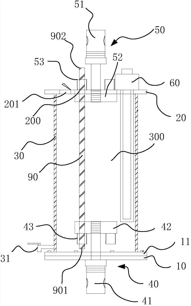
[0028] Such as figure 1 As shown, the rod load holding test device provided by an embodiment of the present invention is used to perform a load holding test on the rod 90. The rod 90 has a first end 901 and a second end 902 opposite to each other. The rod 90 may be a type of workpiece made of glass or metal. In an embodiment, the rod 90 is a glass fiber rib.
[0029] The rod load holding test device includes a tray 10, a cover plate 20, a side wall 30, a first connecting component 40 and a second connecting component 50.
[0030] The side wall 30 is arranged between the tray 10 and the cover plate 20, the bottom end of the side wall 30 is fixedly connected to the tray 10, and the cover plate 20 is covered on the top end of the side wall 30 to prevent liquid from volatilizing during use. The tray 10, the cover plate 20 and the side wall 30 enclose a accommodating cavity 300 for placing the rod 90 to be tested and a liquid reflecting the working environment of the rod 90 (not shown), the liquid may be, for example, an acidic liquid or an alkaline liquid , In order to reflect the real environment of the rod 90 in actual working conditions, so that the test result of the rod 90 is more reliable.
[0031] The first connecting component 40 is combined with the tray 10 to fix the first end 901 of the rod 90, the second connecting component 50 is combined with the cover 20 to fix the second end 902 of the rod 90, the first connecting component 40 and the second The two connecting components 50 jointly apply force to the rod 90 to make the rod 90 bear a certain load, so as to simulate the actual working state of the rod 90.
[0032] The first connecting assembly 40 includes a first connecting head 41, a first fixing plate 42 and a first clip 43.
[0033] The first connecting head 41 has an operating end 411 located outside the accommodating cavity 300 and a connecting end located in the accommodating cavity 300. The first fixing plate 42 is disposed in the accommodating cavity 300 and connected to the first connecting head 41. The connecting end 412 is fixedly connected.
[0034] Also refer to figure 2 In one embodiment, the first connecting head 41 is a screw connecting head. The first connector 41 includes an operating end 411, an opposite connecting end 412, and an abutting portion 413 disposed between the operating end 411 and the connecting end 412. The size of the abutting portion 413 in the radial direction is larger than that of the operating end 411, The size of the end 412 in the radial direction. The operating end 411 is screwed to the abutting portion 413, so that when the operating end 411 rotates relative to the abutting portion 413, the connecting end 412 is driven to rotate. A thread is provided on the connecting end 412. The connecting end 412 passes through the tray 10 to reach the accommodating cavity 300.
[0035] It can be understood that, in another embodiment, the entire first connector 41 may be integrally formed with the tray 10. In this case, the operating end 411 and the abutting portion 413 of the first connecting head 41 are located outside the accommodating cavity 300; the connecting end 412 is located in the accommodating cavity 300 and is fixedly connected to the first fixing plate 42.
[0036] In other embodiments, a corresponding perforation may be provided on the tray 10 for the connecting end 412 to pass through, and the perforation is sealed to prevent liquid leakage.
[0037] Also refer to image 3 with Figure 4 In a specific embodiment, the first fixing plate 42 is provided with a threaded hole 421 for the connecting end 412 of the first connector 41 to be screwed in, so that the first fixing plate 42 is screwed to the first The connector 41 is fixedly connected.
[0038] Further, a connecting hole 420 is provided on the first fixing plate 42 for the first end 901 of the rod 90 to pass through, and the first clip 43 is provided on the first fixing plate 42 for fixing the first end of the rod 90. One end 901.
[0039] Further, the connecting hole 420 on the first fixing plate 42 is a tapered hole. The small end of the tapered hole faces the bottom end of the side wall 30, that is, toward the tray 10, and the large end of the tapered hole faces the top end of the side wall 30, that is, toward the inside of the containing cavity 300 or the cover plate 20. The diameter of the small end of the tapered hole can be smaller or slightly smaller than the diameter of the first end 901 of the rod 90, so that when the rod 90 is inserted into the connecting hole 420, the rod 90 can be affected by the friction between the two. Initially fixed.
[0040] Further, a plurality of connecting holes 420 are provided on the first fixing plate 42. A plurality of connecting holes 420 are distributed around the threaded hole 421. The multiple connecting holes 420 can be used to connect multiple different rods 90 so as to realize the simultaneous test of the multiple rods 90.
[0041] The second connecting assembly 50 includes a second connecting head 51, a second fixing plate 52, and a second clip 53. The second connecting head 51 includes an operating end located outside the accommodating cavity 300 and connected to the second fixing plate 52 The second fixing plate 52 passes through the cover plate 20, the second fixing plate 52 is provided with a connecting hole 200 for the second end 902 of the rod 90 to pass through, and the second clip 53 is arranged on the second fixing plate 52 is used to fix the second end 902 of the rod 90.
[0042] The structure of the second connecting head 51 may be the same as the structure of the first connecting head 41, which will not be described in detail. The connecting end of the second connecting head 51 is fixedly connected to the second fixing plate 52. The cover plate 20 is provided with a through hole for the second fixing plate 52 to pass through. Similar to the threaded holes 421 provided on the first fixing plate 42, corresponding threaded holes are also provided on the second fixing plate 52 to be fixedly connected to the connecting end of the second connector 51.
[0043] The structure of the second fixing plate 52 is the same as the structure of the first fixing plate 42. Similar to the connecting hole 420 provided on the first fixing plate 42, the second fixing plate 52 is also provided with a corresponding connecting hole 200 for the second end 902 of the rod 90 to pass through. The structure of the second clip 53 is the same as that of the first clip 43. The second clip 53 fixes the second end 902 of the rod 90 on the second fixing plate 52.
[0044] Similarly, the connecting hole 200 on the second fixing plate 52 may also be a tapered hole. The small end of the tapered hole faces the top end of the side wall 30, and the large end of the tapered hole faces the bottom end of the side wall 30, that is, faces the accommodating cavity 300. The diameter of the small end of the tapered hole can be smaller or slightly smaller than the diameter of the second end 902 of the rod 90, so that when the rod 90 is inserted into the connecting hole 200, the rod 90 can be affected by the friction between the two. Initially fixed.
[0045] Further, corresponding to the plurality of connecting holes 420 provided on the first fixing plate 42, a plurality of connecting holes 200 are also provided on the second fixing plate 52, and the connecting holes 200 on the second fixing plate 52 are connected to the first The connecting holes 420 on the fixing plate 42 correspond one to one. Each pair of connecting holes 200 and 420 is used to penetrate a first end 901 and a second end 902 of a corresponding rod 90.
[0046] When the rod 90 is subjected to a load holding test using the above rod load holding test device, the first end 901 of the rod 90 penetrates the first fixing plate 42 and is fixed on the first fixing plate 42 by the first clip 43 , The second end of the rod 90 passes through the second fixing plate 52 and is fixed on the second fixing plate 52 by the second clip 53. By stretching the operating end 411 of the first connector 41 or the second connector 51, the rod 90 can be subjected to corresponding stress, so that the rod 90 can bear the load. After that, a working fluid can be placed in the containing cavity 300 to simulate the acidic or alkaline working environment of the rod 90. Therefore, when the device of the present invention is used for testing, the rod 90 is immersed in the working fluid while carrying the load. The simulated environment is closer to the actual working environment of the rod 90, so that the analysis of the rod 90 can be more accurate result.
[0047] In some embodiments, in order to facilitate the observation of changes in the rod 90 during the test, the side wall 30 is set to be transparent. For example, the side wall 30 may be made of borosilicate glass, which is resistant to acids and alkalis and can be adapted to Various working fluids. In other embodiments, an observation window may be provided on the side wall 30.
[0048] In some embodiments, a heating rod 60 is passed through the cover plate 20, and the heating rod 60 at least partially extends into the accommodating cavity 300. The heating rod 60 can heat the working fluid to simulate the actual working environment temperature of the rod 90. Further, the heating rod 60 is a self-controlling temperature heating rod. When the working fluid reaches a predetermined temperature, it can stop and continue to heat up, making the load holding test more automated and intelligent.
[0049] Further, the cover plate 20 is provided with a liquid filling hole 201; the side wall 30 and/or the tray 10 is provided with a liquid drain valve 31. The working liquid can enter the containing cavity 300 from the liquid filling hole 201. The drain valve 31 can drain the working fluid in the containing cavity 300.
[0050] Further, the tray 10 is a flange plate. Also refer to figure 1 with Figure 5 , The tray 10 is further provided with a flange ring 11, the flange ring 11 is sleeved with the side wall 30, and the tray 10, the flange ring 11 and one end of the side wall 30 are hermetically connected. The flange ring 11 and the tray 10 can be fixedly connected by quick-installation bolts.
[0051] The rod load holding test device provided by the present invention can be used in conjunction with a testing machine. The first connecting head 41 of the rod load holding test device is connected to the first fixed end of the testing machine. Specifically, the first connecting head 41 The abutting portion 413 is connected to the first fixed end of the testing machine, and the second connecting head 51 of the rod load holding test device is connected to the second fixed end of the testing machine. Specifically, the abutting portion of the second connecting head 51 can be connected 413 is connected to the second fixed end of the testing machine. Thus, by stretching the operating ends 411 of the first and second connecting heads 41 and 51, a load can be applied to the rod 90.
[0052] The above are only the preferred embodiments of the present invention and are not intended to limit the present invention. Any modification, equivalent replacement and improvement made within the spirit and principle of the present invention shall be included in the protection of the present invention. Within range.

PUM

no PUM

Description & Claims & Application Information

We can also present the details of the Description, Claims and Application information to help users get a comprehensive understanding of the technical details of the patent, such as background art, summary of invention, brief description of drawings, description of embodiments, and other original content. On the other hand, users can also determine the specific scope of protection of the technology through the list of claims; as well as understand the changes in the life cycle of the technology with the presentation of the patent timeline. Login to view more.

Similar technology patents

Android application biometric authentication security method based on static detection

ActiveCN114077728AGood analytical performanceThe analysis result is accurateDecompilation/disassemblyDigital data authenticationThird partyAndroid app
Owner:UNIV OF ELECTRONIC SCI & TECH OF CHINA

Classification and recommendation of technical efficacy words

Why Eureka
Try Eureka