Flap for vacuum cleaner suction head

A technology of vacuum cleaners and valves, applied in the direction of vacuum cleaners, suction nozzles, cleaning equipment, etc.

Active Publication Date: 2015-08-19
SEB SA
View PDF7 Cites 7 Cited by
  • Summary
  • Abstract
  • Description
  • Claims
  • Application Information

AI Technical Summary

Problems solved by technology

In this case there is no control over the velocity

Method used


Image

  • Flap for vacuum cleaner suction head
  • Flap for vacuum cleaner suction head
  • Flap for vacuum cleaner suction head

Examples


Embodiment Construction

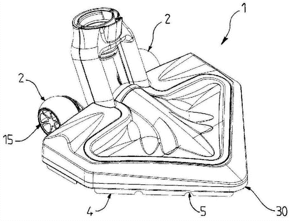
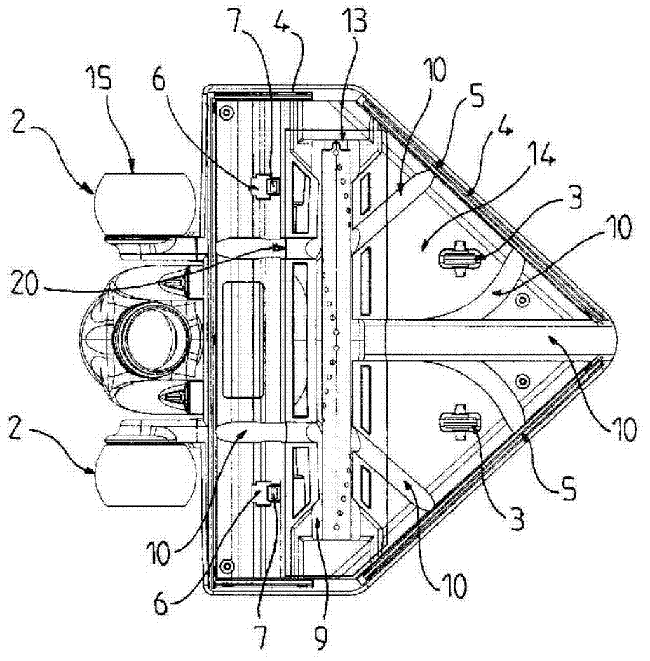
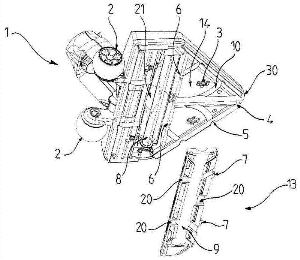
[0020] figure 1 Shown is a suction head 1 for a vacuum cleaner comprising a base 14 and a wheel 2 whose rolling belt 15 is shaped in the form of a roller and which defines the minimum distance from the base 14 when the suction head 1 is placed on a slippery floor. ground distance. At least two small wheels 3 are also arranged below the base 14 . The suction head 1 has a triangular overall shape, and the tip 30 of the triangle is positioned in the direction of movement of the suction head 1 .

[0021] In a particular embodiment, a sealing lip or sealing skirt 4 is arranged around the seat 14 . The sealing skirt 4 eliminates leakage between the smooth ground and the base 14, and for good suction efficiency, the sealing skirt 4 is perforated opposite the duct 10 of the base 14 so that it is sucked under the base 14 The air only enters directly into the duct 10 of the base 14. This results in a good suction of dirt from the floor since the air velocity is greatest in the duct ...


PUM


Abstract

The present invention relates to a vacuum cleaner suction head (1) comprising a soleplate (14) which has at least one suction duct (10) that is open towards the ground and which converges from an outer rim of the soleplate (14) towards a suction orifice (9) connected in terms of air flow to a vacuum cleaner, the soleplate (14) of which comprises a removable flap (13) which includes the suction orifice (9) and at least one suction duct (20) that is open towards the ground and arranged opposite said at least one suction duct (10) of the soleplate (14).

Description

technical field [0001] The invention generally relates to a suction head of a vacuum cleaner equipped with a shutter for accessing a motorized brush. Background technique [0002] Hitherto, a suction head for a vacuum cleaner is known in the prior art, for example as described in document FR1158711, wherein the suction head disclosed comprises a lower base comprising at least one suction duct open towards the ground And converge from the outer edge of the base toward the suction hole connected to the vacuum cleaner. The disclosed suction head is triangular in shape and in one variation it may comprise a motorized brush. However, this system has the disadvantage of not having any protective elements for the electric brushes, which are in direct contact with the ground. In the case of the attached figures, it can be observed that when the suction head is used in a special configuration, the motorized brush is damaged when the element comes into contact with the axis of rotat...

Claims


Application Information

Patent Timeline
IPC IPC(8): A47L9/02A47L9/04
CPCA47L9/0455A47L9/02A47L9/0477
Inventor 阿兰·索昂赛里·吉诺埃里克·格莱
Owner SEB SA
Why Eureka
Try Eureka