
Lighting system

A lighting system and lighting unit technology, applied in the field of lighting systems, can solve problems such as the limitation of design possibilities of the light track system, and achieve the effect of simple, fast and fast installation

Active Publication Date: 2017-02-15
迪特马尔迪克斯 +1
View PDF8 Cites 1 Cited by
  • Summary
  • Abstract
  • Description
  • Claims
  • Application Information

AI Technical Summary

Problems solved by technology

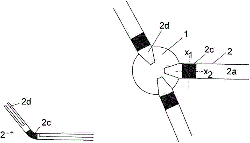
[0007] The design possibilities of known light rail systems are very limited, since they can usually only be constructed in a straight line or in a plane on the one hand or only at certain preset angles on the other hand

Method used


Image

  • Lighting system
  • Lighting system
  • Lighting system

Examples


Embodiment approach

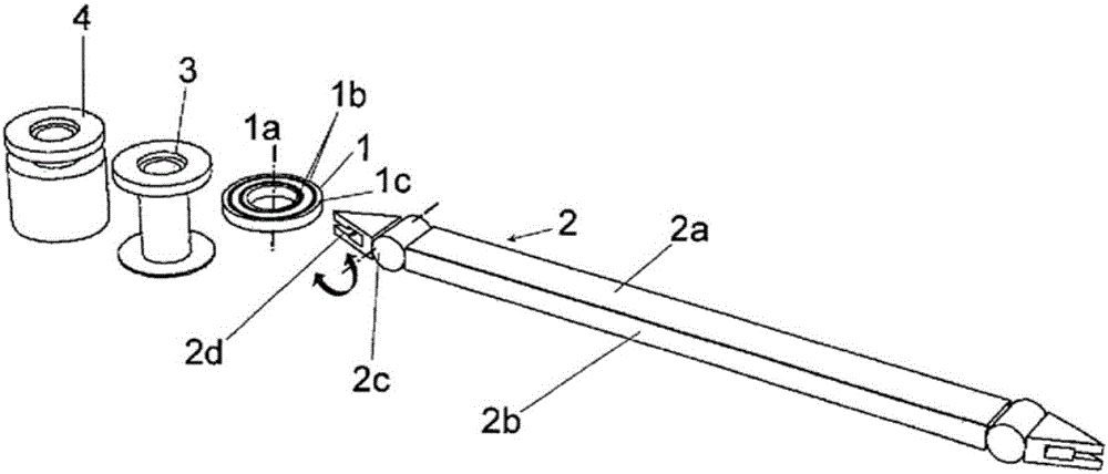
[0068] Special connectors 3 provide fastening possibilities for installation on walls or ceilings. Additionally or alternatively, it is also conceivable to supply current to the connector 4 in the system.

[0069] In addition, the connector may also provide for securing of other lighting units around the main body of the central axis or outside of the main body portion.

[0070] The connectors can be connected with other connectors, whereby more lighting units can be fixed.

[0071] Connectors can also be illuminated (with lighting fixtures).

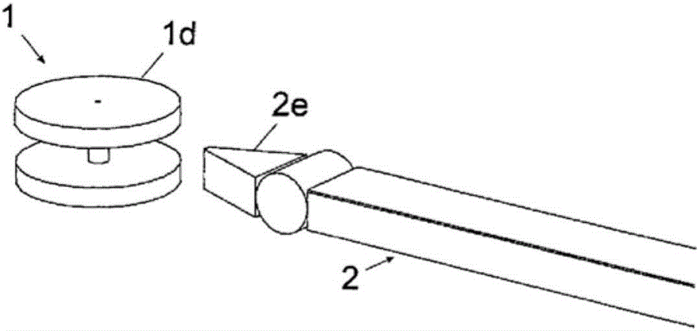
[0072] Light rails, also called lighting units, correspond to the invention in particular:

[0073] Applies to components that structurally connect connectors and conduct current. These parts are preferably illuminated (eg aluminum profile rail 2b with embedded LED strips).

[0074] Other implementations:

[0075] The lighting unit can also be planar and connect three or more connectors. These corners form the ends to which the co...


PUM

PropertyMeasurementUnit
Rotation rangeaaaaaaaaaa

Abstract

The invention relates to an lighting system (5) with at least one lighting unit (2, 2i) containing a light segment (2a), which is configured to receive at least one lighting means or has at least one lighting means, and containing at least one connection element (2d-2h) which is electrically conductive at least in some sections and which is mechanically and electrically connected to an end of the light segment (2a), and comprising at least one connector (1, 3, 4), which has at least one element (1c-1e) that encircles a connector central axis (1a) and at least one electric conductor (1b) that is mechanically connected to the encircling element (1c-1d) or is formed by the encircling element (1c-1e). The connection element (2d-2h) of the lighting unit (2, 2i) is mechanically connected to the encircling element (1c-1e) of the connector (1, 3, 4), and the at least one lighting unit (2, 2i) is thus mechanically and electrically connected to the connector (1, 3, 4). The aim of the invention is to reduce the assembly complexity in a lighting system (5). According to the invention, this is achieved in that the lighting unit (2, 2i) can be arranged with the connector (1, 3, 4) in different positions around the connector central axis (1a), the lighting unit (2, 2i) is mechanically and electrically connected to the connector (1, 3, 4) in each position, and multiple lighting units (2, 2i) are mechanically and electrically connected to a common connector (1, 3, 4).

Description

technical field [0001] The invention relates to a lighting system with at least one lighting unit comprising a lamp segment, which is provided for receiving at least one lighting fixture or has at least one lighting fixture, and at least one connecting part. at least in sections electrically conductive and mechanically and electrically connected to the lamp section at the end of the lamp section; at least one connector having at least one part surrounding the central axis of the connector and at least one Electrical conductor mechanically connected to or formed by a circular part, wherein the connecting part of the lighting unit is mechanically connected to the circular part of the connector and thus at least one lighting unit is mechanically connected to the connector and electrically connected. [0002] The invention relates in particular to a lighting system having: a plurality of components (such as lighting units, in particular light rails), which can accommodate lightin...

Claims


Application Information

Patent Timeline
IPC IPC(8): F21S2/00F21V23/06F21V21/30F21Y115/10
CPCF21S2/005F21V21/30F21V23/06F21Y2103/10F21Y2115/10F21V21/002F21Y2103/00F21S2/00F21S4/28F21S8/038F21S8/066F21V17/10F21V21/005F21V21/28
Inventor 迪特马尔·迪克斯
Owner 迪特马尔迪克斯
Learn More