Respirator triggering time parameter monitoring method

A technology for triggering time and parameter monitoring, applied in the field of ventilators

Inactive Publication Date: 2015-09-02
BEIJING AEONMED
View PDF8 Cites 2 Cited by
  • Summary
  • Abstract
  • Description
  • Claims
  • Application Information

AI Technical Summary

Problems solved by technology

However, there is currently no ventilator that monitors the trigger time parameters of the ventilator itself. The trigger time can no

Method used


Image

  • Respirator triggering time parameter monitoring method
  • Respirator triggering time parameter monitoring method

Examples


Embodiment Construction

[0014] Embodiments of the present invention are described in detail below, examples of which are shown in the drawings, wherein the same or similar reference numerals designate the same or similar elements or elements having the same or similar functions throughout. The embodiments described below by referring to the figures are exemplary and are intended to explain the present invention and should not be construed as limiting the present invention.

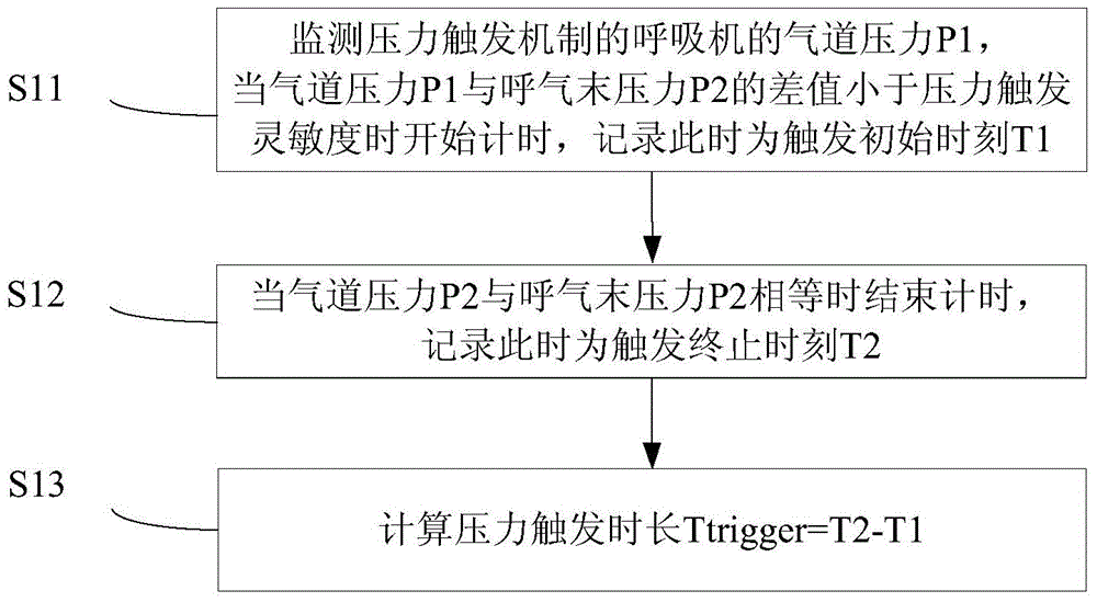
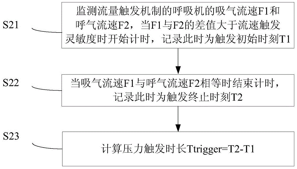
[0015] The first aspect of the present invention proposes a trigger time parameter monitoring method suitable for a ventilator whose inspiratory trigger mechanism is a pressure trigger mechanism, such as figure 1 As shown, the following steps may be included:

[0016] S11. Monitor the airway pressure P1, and start timing when the difference between the airway pressure P1 and the end-expiratory pressure P2 is less than the pressure trigger sensitivity, and record this as the trigger initial time T1.

[0017] S12. Stop timing when...


PUM

PropertyMeasurementUnit
Sensitivityaaaaaaaaaa

Abstract

The invention discloses a respirator triggering time parameter monitoring method. For a respirator having a pressure trigger mechanism, the method comprises following steps: monitoring the airway pressure P1; starting to time when the difference between the airway pressure P1 and the end-expiratory pressure P2 is less than a pressure trigger sensitivity and recording the moment as a trigger initial moment T1; stopping timing when the airway pressure P1 is equal to the end-expiratory pressure P2 and recording the moment as a trigger ending moment T2; and calculating the triggering time according to a formula that Ttrigger = T2 - T1. For a respirator having a flow triggering mechanism, the method comprises following steps: simultaneously monitoring the inspiration flow speed F1 and the expiration flow speed F2; starting to time when the difference between the inspiration flow speed F1 and the expiration flow speed F2 is larger than a flow speed trigger sensitivity and recording the moment as the trigger initial moment T1; stopping timing when the inspiration flow speed F1 is equal to the expiration flow speed F2 and recording the moment as the trigger ending moment T2; and calculating the triggering time according to the formula that Ttrigger = T2 - T1. The method is simple and reliable.

Description

technical field [0001] The invention belongs to the technical field of ventilators, and in particular relates to a method for monitoring trigger time parameters of a ventilator. Background technique [0002] At present, there are two types of inspiratory triggering mechanisms of ventilators: pressure triggering mechanism and flow triggering mechanism. Since the ventilator and artificial airway can produce additional resistance, in order to reduce the extra work of the patient, the trigger sensitivity should be set at a more sensitive level. According to preliminary clinical research, compared with pressure triggering, flow triggering can further reduce the patient's work of breathing and make patients more comfortable. However, there is currently no ventilator that monitors the trigger time parameters of the ventilator itself. The trigger time can not only help doctors set an appropriate trigger sensitivity, but also evaluate the response speed of a ventilator to patient tr...

Claims


Application Information

Patent Timeline
IPC IPC(8): A61M16/00
Inventor 刘建军
Owner BEIJING AEONMED
Why Eureka
Try Eureka