
Displacement monitoring device and method for reinforcement and reconstruction engineering

An engineering monitoring and position-corresponding technology, applied in measuring devices, mechanical measuring devices, mechanical devices, etc., can solve problems such as repair and maintenance difficulties, damage to precision instruments, large manpower and material resources, etc., and achieve simple and reliable monitoring methods and timely feedback , The effect of less physical input of manpower

Pending Publication Date: 2022-06-24
BCEG INT
View PDF0 Cites 0 Cited by
  • Summary
  • Abstract
  • Description
  • Claims
  • Application Information

AI Technical Summary

Problems solved by technology

The former needs to invest a lot of manpower and material resources in real-time monitoring and has large errors. Although the latter has a high degree of automation and precision and requires less manpower, the equipment is expensive, and if the project is located overseas, it will face the long-distance transportation of precision instruments There may be damage in the process, and problems such as overseas repair and maintenance difficulties
[0004] This shows that the above-mentioned existing monitoring device and monitoring method obviously still have inconvenience and defects in structure and use, and need to be further improved urgently.

Method used


Image

  • Displacement monitoring device and method for reinforcement and reconstruction engineering
  • Displacement monitoring device and method for reinforcement and reconstruction engineering
  • Displacement monitoring device and method for reinforcement and reconstruction engineering

Examples


Embodiment Construction

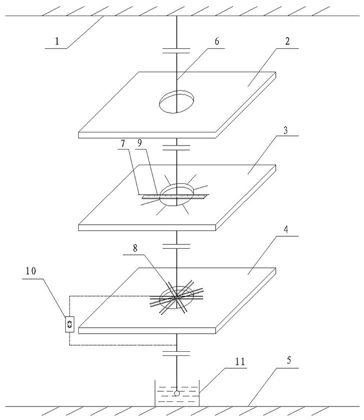
[0030] see combining figure 1 and figure 2 , The present invention provides a monitoring device for reinforcement and reconstruction engineering, including a wire sinker 6 , a trigger and an alarm 10 .

[0031] The wire of the wire pendant 6 is made of conductive material, and the end of the wire pendant 6 is connected with a heavy object, so that the wire pendant 6 is always vertical when it hangs down naturally. The wire pendant 6 is suspended on the roof 1 of the structure to be tested, and there are pay-off holes in the corresponding positions of the first floor 2, the first underground floor 3 and the second underground floor 4 of the tested structure. The drop 6 passes through the payout holes of the first floor slab 2 , the first underground floor slab 3 and the second underground floor slab 4 in sequence, and hangs down into the barrel 11 of the third underground floor 5 . Preferably, the barrel 11 is filled with oil, which plays a damping role in reducing the swing...


PUM


Abstract

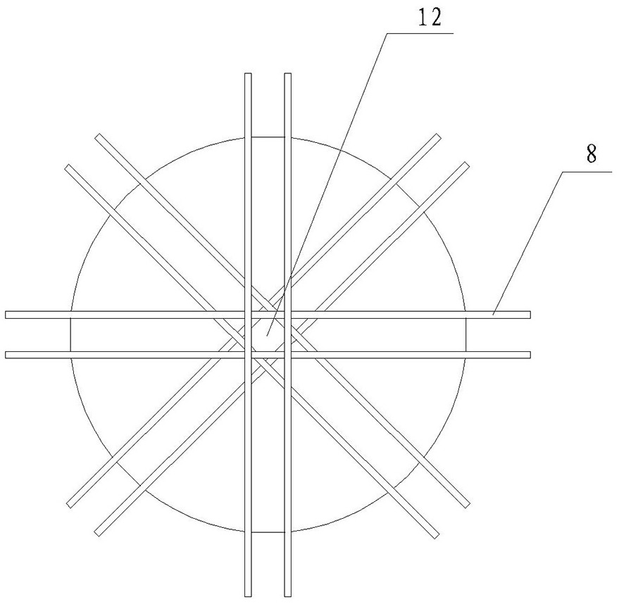
The invention discloses a monitoring device and method for reinforcement and reconstruction engineering, the monitoring device comprises a plummet, a trigger and an alarm, and the corresponding positions of a first floor, a first underground floor and a second underground floor of a detected structure are provided with pay-off holes; the line pendant is hung on a roof, sequentially penetrates through pay-off holes of a first floor, a first underground floor and a second underground floor and is perpendicular to a barrel of a third underground floor, the trigger comprises a plurality of conductive wires, every two conductive wires are parallelly arranged at intervals to form a group, the conductive wires are horizontally and crosswise erected at the pay-off holes of the second underground floor, and the conductive wires are connected with the trigger. The plummet penetrates through a center hole defined by the conductive wires, the conductive wires and the plummet are connected with the alarm through wires to form a closed loop, and the alarm is triggered to give an alarm when the plummet touches any conductive wire. The system is simple and reliable in structure, low in cost, small in input of manpower and physical power, accurate in monitoring data, timely in feedback and capable of effectively achieving the inclination, displacement and settlement monitoring function of the building.

Description

technical field [0001] The invention relates to the technical field of building reinforcement and reconstruction projects, in particular to a displacement monitoring device and method for reinforcement and reconstruction projects. Background technique [0002] During the construction of the processing project, part of the existing structure will be demolished and the section will be enlarged, as well as the chiseling and grinding of the existing concrete surface of the part to be reinforced, which may cause the original structure to tilt, settle and move. , Especially for projects located in coastal areas, because the base soil is sandy soil, the construction will disturb the original structure more. Therefore, during the construction process, it is necessary to monitor the state of the original structure in real time and adjust the construction plan in time. [0003] The traditional monitoring methods include using a total station or a plumb bob and a level to monitor the d...

Claims


Application Information

Patent Timeline
IPC IPC(8): G01B5/02
CPCG01B5/02
Inventor 王朝瑞张建普杜志磊
Owner BCEG INT
Learn More