A PTFE rubber-plastic composite self-lubricating O-ring

A teflon, O-ring technology, applied in the direction of engine sealing, engine components, mechanical equipment, etc., can solve the problems of easy wear, high friction coefficient of pure rubber elastomer, difficult to withstand the dynamic sealing requirements of moving shafts, etc. , to maintain the balance of elasticity index, elasticity and wear resistance

Active Publication Date: 2018-02-13
程麒 +1
View PDF7 Cites 0 Cited by
  • Summary
  • Abstract
  • Description
  • Claims
  • Application Information

AI Technical Summary

Problems solved by technology

Due to the large friction coefficient of pure rubber elastic body, it is easy to wear in the field of dynamic sealing, and it is difficult to withstand the dynamic sealing requirements of millions of reciprocating and rotating motion shafts.

Method used


Image

  • A PTFE rubber-plastic composite self-lubricating O-ring
  • A PTFE rubber-plastic composite self-lubricating O-ring
  • A PTFE rubber-plastic composite self-lubricating O-ring

Examples


Embodiment 1

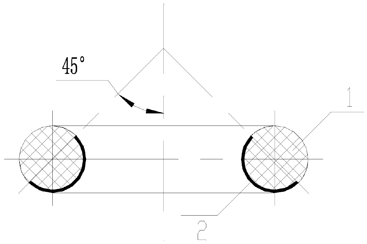
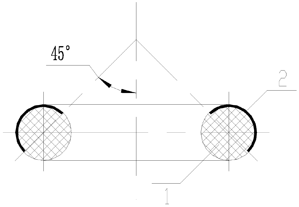
[0017] Such as figure 1 and figure 2 As shown, it is a polytetrafluoroethylene rubber-plastic composite self-lubricating O-ring used as a shaft, which includes a ring-shaped sealing ring body, which is composed of rubber elastic body 1 and compounded on the rubber elastic body 1 The ring-shaped polytetrafluoroethylene covering body 2 on the ring-shaped working surface is composed of. The thickness of the polytetrafluoroethylene covering body 2 is 0.05mm-2mm, the inner diameter specification of the polytetrafluoroethylene rubber-plastic composite self-lubricating O-ring is Φ3mm-Φ1000mm, and the section specification is Φ2mm-Φ100mm. The polytetrafluoroethylene covering body 2 has a semicircular cross section and is a layer of semicircular thin slices. On the cross section of the sealing ring body, the line between the two ends of the polytetrafluoroethylene covering body 2 forms an included angle of 45° with the plumb line. The polytetrafluoroethylene covering body 2 is loca...

Embodiment 2

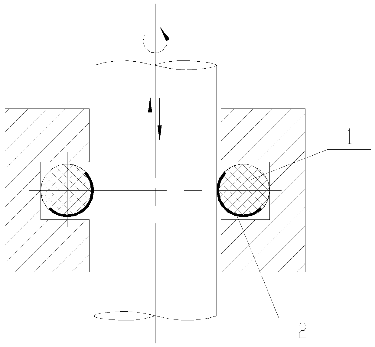
[0019] Such as image 3 and Figure 4 As shown, it is a polytetrafluoroethylene rubber-plastic composite self-lubricating O-ring used as a hole, which includes a ring-shaped sealing ring body, which is composed of rubber elastic body 1 and compounded on the rubber elastic body 1 The ring-shaped polytetrafluoroethylene covering body 2 on the ring-shaped working surface is composed of. The thickness of the polytetrafluoroethylene covering body 2 is 0.05mm-2mm, the inner diameter specification of the polytetrafluoroethylene rubber-plastic composite self-lubricating O-ring is Φ3mm-Φ1000mm, and the section specification is Φ2mm-Φ100mm. The polytetrafluoroethylene covering body 2 has a semicircular cross section and is a layer of semicircular thin slices. On the cross section of the sealing ring body, the line between the two ends of the polytetrafluoroethylene covering body 2 forms an included angle of 45° with the plumb line. The polytetrafluoroethylene covering body 2 is locat...


PUM


Abstract

The invention discloses a teflon rubber-plastic composite self-lubricating O-shaped sealing ring which comprises a sealing ring body. The sealing ring body comprises a rubber elastic body and a teflon wrapping body composited on the rubber elastic body. When the sealing ring is used as the sealing ring for a shaft, the teflon wrapping body is located on the inner side of the rubber elastic body, and on the cross section of the sealing ring body, the connecting line between the edges at two ends of the teflon wrapping body and a plumb line form a 45-degree included angle to allow the inner-side rubber elastic body in friction contact with the shaft to be wear resistant. When the sealing ring is used as the sealing ring for a hole, the teflon wrapping body is located on the outer side of the rubber elastic body, and on the cross section of the sealing ring body, the connecting line between the edges at two ends of the teflon wrapping body and a plumb line form a 45-degree included angle to allow the outer-side rubber elastic body in friction contact with a hole wall to be wear resistant. The elasticity and toughness of the sealing ring are guaranteed by the rubber elastic body, and the wear resistance and self-lubricating performance of the sealing ring are guaranteed by the teflon wrapping body.

Description

technical field [0001] The invention relates to the field of reciprocating and rotating dynamic seals, in particular to a polytetrafluoroethylene rubber-plastic composite self-lubricating O-ring. Background technique [0002] O-ring seals are the core components of cylinders, oil cylinders, hydraulic reversing valves, and pneumatic reversing valves. The stability of its working performance is closely related to the wear resistance of such parts. Traditional O-rings are made of pure rubber elastomers. Due to the large friction coefficient of pure rubber elastic body, it is easy to wear in the field of dynamic sealing, and it is difficult to withstand the dynamic sealing requirements of millions of reciprocating and rotating motion shafts. Contents of the invention [0003] In order to solve the defects of the above-mentioned technologies, the present invention provides a polytetrafluoroethylene rubber-plastic composite self-lubricating O-ring. [0004] The technical schem...

Claims


Application Information

Patent Timeline
Patent Type & Authority Patents(China)
IPC IPC(8): F16J15/18
CPCF16J15/18
Inventor 程麒程峰
Owner 程麒
Why Eureka
Try Eureka