

Drive belt provided with a ring set with steel rings having a nitride layer and method for determining a thickness of such a nitride layer
A technology of nitrided layer and transmission belt, which is applied in the field of transmission belt, can solve the problems of not being directly applicable or not suitable for transmission belt without further consideration
- Summary
- Abstract
- Description
- Claims
- Application Information
AI Technical Summary
Problems solved by technology
Method used
Image

Examples
Embodiment Construction
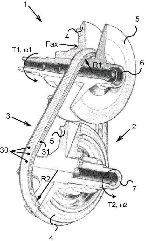
[0027] figure 1 Shown is the center section of an existing continuously variable transmission or CVT typically applied in a motor vehicle's drive train between its engine and drive wheels. The variator comprises two pulleys 1, 2 each provided with two conical pulley discs 4, 5 in which a substantially V-shaped groove is defined Between 4, 5, one of the two conical pulley disks 4, 5 can be axially aligned along the corresponding pulley shaft 6, 7 on which the disk 4 is arranged. to move. A drive belt 3 surrounds the pulleys 1 , 2 to transmit the rotational movement ω and the accompanying torque T from one pulley 1 , 2 to the other pulley 2 , 1 . The variator usually also comprises an activation device which exerts on said at least one disc 4 an axially oriented clamping force Fax directed towards the respective other pulley disc 5, so that the belt 3 is clamped on the disc 4, the disc between 5. And, the transmission (speed) ratio between the rotational speed of the driven ...
PUM
| Property | Measurement | Unit |
|---|---|---|
| Thickness | aaaaa | aaaaa |
| Thickness | aaaaa | aaaaa |
| Thickness | aaaaa | aaaaa |
Abstract
Description
Claims
Application Information