Steam mop

A steam and mop technology, applied in the field of mops, can solve problems such as use troubles

Active Publication Date: 2015-09-09
TSANN KUEN ZHANGZHOU ENTERPRISE CO LTD
View PDF6 Cites 11 Cited by
  • Summary
  • Abstract
  • Description
  • Claims
  • Application Information

AI Technical Summary

Problems solved by technology

However, when mopping the floor, it is often necessary to change the angle between the mop handle and the mop head to avoid obstacles, but this will accidentally change the way the steam is ejected, which is quite disturbing in use

Method used


Image

  • Steam mop
  • Steam mop
  • Steam mop

Examples


Embodiment Construction

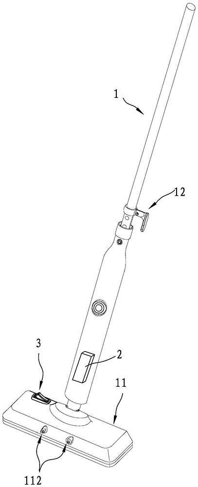
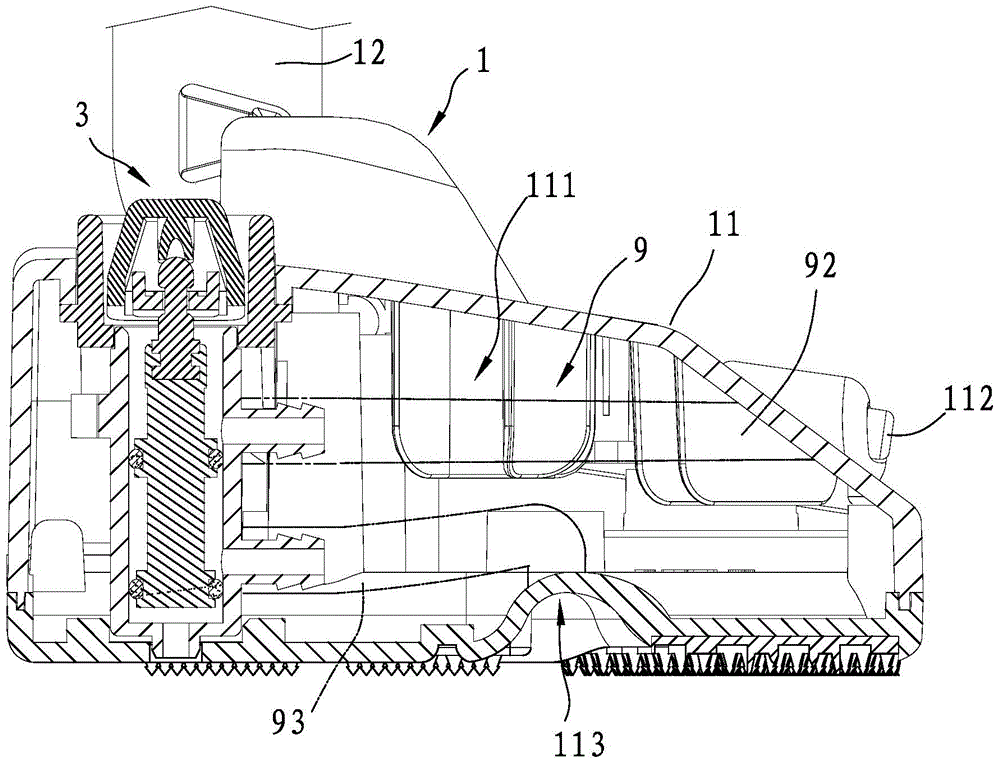
[0020] refer to figure 1 and figure 2 , an embodiment of the steam mop of the present invention includes a mop body 1 , a steam element 2 connected to the mop body 1 and capable of generating steam, and a control system 3 arranged in the mop body 1 . The mop body 1 includes a hollow mop head 11 capable of leaving steam, and a mop handle 12 capable of being held and connected to the mop head 11 . The mop head 11 defines an installation space 111 for the control system 3 to be placed, and has two side steam ports 112 and a bottom steam port 113 respectively located at the front side and the bottom edge for steam to leave. In practice, the mop head 11 may also have only one side steam port 112, not limited to two. The steam element 2 is arranged in the mop handle 12. As for how the steam element 2 generates steam and how to transport the steam to the mop head 11, it is a known prior art and is not the focus of the present invention. This is not detailed.

[0021] refer to ...


PUM


Abstract

A steam mop comprises a mop body, a steam part connected with the mop body, and a control system arranged in a mop head. The mop body comprises the hollow mop head which can allow steam to be exhausted, and a mop handle connected with the mop head. The mop head is provided with a lateral steam port and a bottom steam port. The control system comprises a first valve seat, a second valve seat communicated with the first valve seat, a switching unit in the first valve seat, and a valve rod penetrating through the second valve seat. The switching unit is provided with a button. The first state and the second state of the control system can be switched by pressing the button. When the control system is in the first state, steam flows through the second valve seat and then is exhausted out of the bottom steam port; when the control system is in the second state, steam flows through the second valve seat and then is exhausted out of the lateral steam port. The steam mop has the advantages of switching the states conveniently and not disturbing a user to mop the floor after switching the states.

Description

technical field [0001] The invention relates to a mop, in particular to a steam mop capable of generating steam. Background technique [0002] Announcement No. CN100593998C patent case discloses a kind of steam mop. The characteristic of the steam mop is that the steam can be ejected from the front and the bottom, and whether the steam is ejected can be controlled by changing the angle between a mop handle and a mop head of the steam mop. However, when mopping the floor, it is often necessary to change the angle between the mop handle and the mop head to avoid obstacles, but this will accidentally change the way the steam is ejected, which is quite disturbing in use. Therefore, how to design a steam mop that is convenient to switch and does not interfere with the mopping of the floor by the user is a problem to be solved. Contents of the invention [0003] The purpose of the present invention is to provide a steam mop, which is convenient to switch the direction of steam...

Claims


Application Information

Patent Timeline
Patent Type & Authority Applications(China)
IPC IPC(8): A47L11/34A47L11/40
CPCA47L13/225A47L11/4086A47L11/4088F16K31/56
Inventor 刘金永郑真兴
Owner TSANN KUEN ZHANGZHOU ENTERPRISE CO LTD
Why Eureka
Try Eureka