Pad pasting apparatus
A film sticking device and film sticking technology, applied in the direction of packaging, etc., can solve the problems of poor lamination between the film and the workpiece, achieve uninterrupted and continuous film sticking, reduce the defective rate of film sticking, and enhance the strength of the film sticking
Active Publication Date: 2015-09-09
JIANGSU BVM INTELLIGENT TECH
View PDF8 Cites 1 Cited by
- Summary
- Abstract
- Description
- Claims
- Application Information
AI Technical Summary
Problems solved by technology
However, for workpieces whose film surface is not flat, common film laminating devices will have quality problems such as poor lamination of the film and the workpiece.
Method used
View moreImage
Smart ImageViewing Examples

Examples
specific Embodiment
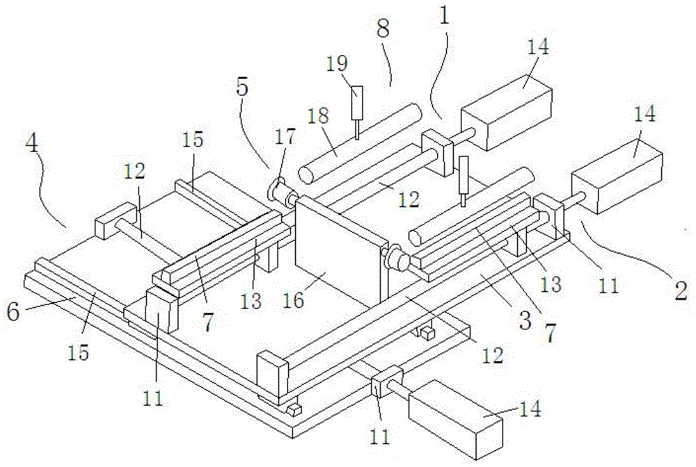
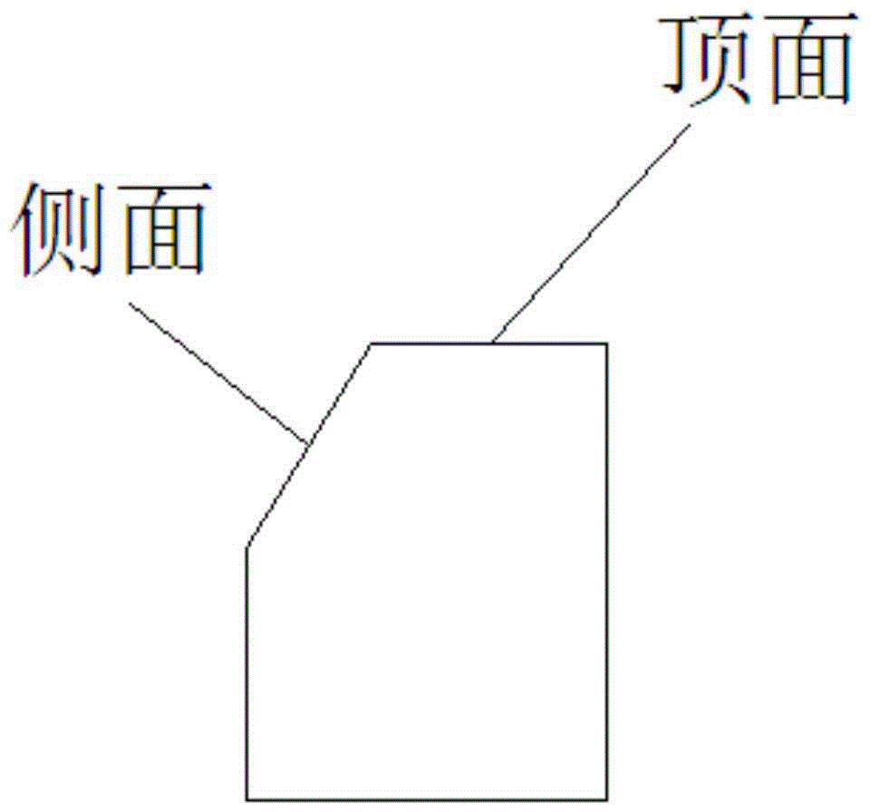
[0016] Specific embodiment: the first film sticking station and the second film sticking station of the transposition mechanism move back and forth, alternately sticking the film under the film peeling mechanism station, and each film sticking station moves to the right to complete the film pressing on the top surface and the side of the workpiece process, then receiving and loading, and so on.
Login to View More PUM
 Abstract
The invention discloses a pad pasting apparatus comprising a first pad pasting work position, a second pad pasting work position, a first base plate, an inversion mechanism and a pad pressing mechanism. The first pad pasting work position and the second pad pasting work position are arranged on the front end and the back end of the first base plate; the first pad pasting work position and the second pad pasting work position both comprises a fixing plate, a lead screw, a work plate and a motor; each work plate can move left to right on the lead screw; the inversion mechanism is formed by a second base plate, a guide rail, a fixing plate, a lead screw and a motor; the bottom surface of the first base plate can move back and forth along the guide rail; and the pad pressing mechanism consists of a positioning plate and a pad pressing roller. With two pad pasting work positions aligned to a pad peeling mechanism, pads can be continuously passed, so pad pasting speed can be improved; besides, with the addition of the pad pressing roller and the side pressing roller, pad pasting speed is enhanced and performance for adaptability to different pressing surfaces is improved; and reject ratio is lowered.
Description
technical field [0001] The invention relates to a film sticking device, which belongs to the technical field of automatic film sticking equipment. Background technique [0002] At present, workpiece filming is the most common process. However, for workpieces whose film surface is not flat, common film laminating devices will have quality problems such as poor lamination of the film and the workpiece. In addition, how to improve the utilization rate of the film stripping machine, so that at one station, the film stripping device can be used to apply film to the workpiece on the film sticking device without stopping is a problem that needs to be solved urgently in this industry. Contents of the invention [0003] Purpose: In order to overcome the deficiencies in the prior art, the present invention provides a film sticking device. [0004] Technical solution: In order to solve the above-mentioned technical problems, the technical solution adopted in the present invention i...
Claims
Login to View More Application Information
Patent Timeline
 Patent Type & Authority Applications(China)
IPC IPC(8): B65B33/02
CPCB65B33/02
Inventor 李相鹏牛福洲杨浩谢明杨李伟马玮城宦智杰
Owner JIANGSU BVM INTELLIGENT TECH
Features
- R&D
- Intellectual Property
- Life Sciences
- Materials
- Tech Scout
- Unparalleled Data Quality
- Higher Quality Content
- 60% Fewer Hallucinations
Learn More Browse by: Latest US Patents, China's latest patents, Technical Efficacy Thesaurus, Application Domain, Technology Topic, Popular Technical Reports.
© 2025 PatSnap. All rights reserved.Legal|Privacy policy|Modern Slavery Act Transparency Statement|Sitemap|About US| Contact US: help@patsnap.com