
A fin arrangement fixture

A technology of fins and fins, applied in the field of evaporators, can solve problems such as leakage, misalignment, falling fins, and unsmooth fins being arranged.

Active Publication Date: 2017-06-09
SUZHOU IND ROBOT TECH
View PDF5 Cites 1 Cited by
  • Summary
  • Abstract
  • Description
  • Claims
  • Application Information

AI Technical Summary

Problems solved by technology

The method of manually inserting the fins requires the operator to hold the fins to arrange the fins, which has high requirements for the personnel on the operation site, the quality of the fins cannot be guaranteed, and problems such as missing and wrong rows are prone to occur, and the efficiency of manual operation is low. It also increases labor costs
However, although the existing sheet arranging device can realize sheet arranging in a non-manual way, the fins are easy to fall out when the sheet arranging action is not performed, causing the fin arranging not to be smooth; in addition, the existing sheet arranging device used The unloading method of the sheet arranging jig can only be used for fins of a specific structure, and cannot be applied to fins of any structure

Method used


Image

  • A fin arrangement fixture
  • A fin arrangement fixture
  • A fin arrangement fixture

Examples


Embodiment Construction

[0016] The preferred embodiments of the present invention will be described in detail below in conjunction with the accompanying drawings, so that the advantages and features of the present invention can be more easily understood by those skilled in the art, so as to define the protection scope of the present invention more clearly.

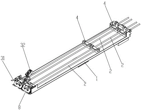
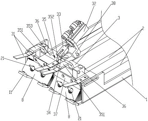
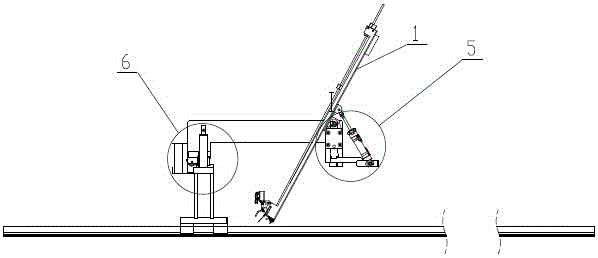
[0017] Such as figure 1 and figure 2 As shown, a fin arranging jig includes a fin loading tray 1 on which a plurality of fin guide rods 2 are arranged, and fins 8 are mounted on the fin guide rods 2 . In this embodiment, the head end of the fin carrier plate 1 has an upwardly bent warped portion 11 , and the head end of the fin guide rod 2 also has an upwardly bent warped head 21 . A fixed plate 3 located above the fin guide bar 2 is provided at the head end of the fin loading tray 1 . The fixing plate 3 is provided with a pressing piece 31 extending outward. The fixed plate 3 at the head end of the fin loading tray 1 is also provided with a ...


PUM


Abstract

The invention discloses a fin arranging clamp which comprises a fin loading disc. The fin loading disc is provided with a plurality of fin guide rods, fins penetrate the fin guide rods, the head end of the fin loading disc is provided with a fixed plate located above the fin guide rods, the fixed plate is provided with a pressing piece extending outwards, and the fixed plate at the head end of the fin loading disc is further provided with a fin anti-leaking cylinder. The fin anti-leaking cylinder is connected with an anti-leaking connecting piece, the anti-leaking connecting piece is connected with a fin anti-leaking part through a rotating shaft, and the fin anti-leaking part is provided with a fin anti-leaking claw extending outwards. The fin arranging clamp can quickly and reliably arrange the fins, the fin arrangement quality is guaranteed, operators' working strength and production cost are reduced, and the production efficiency is improved.

Description

technical field [0001] The invention relates to the technical field of evaporators, in particular to a fin arranging fixture used in the production of finned evaporators. Background technique [0002] When the finned evaporator is produced, the fins need to be inserted into the slots of the mold one by one to arrange the fins. The current way of arranging the films generally adopts the method of manually arranging the films. The method of manually inserting the fins requires the operator to hold the fins to arrange the fins, which has high requirements for the personnel on the operation site, the quality of the fins cannot be guaranteed, and problems such as missing and wrong rows are prone to occur, and the efficiency of manual operation is low. Also increased labor costs. However, although the existing sheet arranging device can realize sheet arranging in a non-manual way, the fins are easy to fall out when the sheet arranging action is not performed, causing the fin arr...

Claims


Application Information

Patent Timeline
Patent Type & Authority Patents(China)
IPC IPC(8): B21D53/04B21D43/04
CPCB21D43/003B21D53/022B21D53/04
Inventor 姜慧锋徐世财陈永祥陈学智
Owner SUZHOU IND ROBOT TECH
Learn More