Automobile tail lamp functional module and LED circuit board installation method thereof

A technology for LED circuit boards and automobile tail lights, which is applied to motor vehicles, road vehicles, signal devices, etc., can solve the problems of affecting the appearance, insufficient space to install LEDs, exposed circuit boards, etc., to achieve light weight, better overall effect and beautiful appearance , the effect of high light utilization

Active Publication Date: 2015-09-16
HASCO VISION TECHNOLOGY CO LTD
View PDF6 Cites 6 Cited by
  • Summary
  • Abstract
  • Description
  • Claims
  • Application Information

AI Technical Summary

Problems solved by technology

[0007] The purpose of the present invention is to provide a functional module of an automobile tail light. In the said automobile tail light functional module, the LED circuit board is arranged on the back of the LED mounting bracket, which deepens the depth of the light guide plate, and is more conducive to the installation and installation of the LED. The uniformity of the lighting effect is used to solve the problem that the LED cannot be installed due to insufficient internal space of the lamp. At the same time, the LED circuit board is placed on the back of the bracket, which fundamentally solves the problem that the circuit board is exposed and affects the appearance, making the light guide plate as good as possible. Deep, so that the lighting effect of taillights is more uniform

Method used


Image

  • Automobile tail lamp functional module and LED circuit board installation method thereof
  • Automobile tail lamp functional module and LED circuit board installation method thereof
  • Automobile tail lamp functional module and LED circuit board installation method thereof

Examples


Embodiment Construction

[0026] The present invention will be described in further detail below in conjunction with the accompanying drawings and specific embodiments.

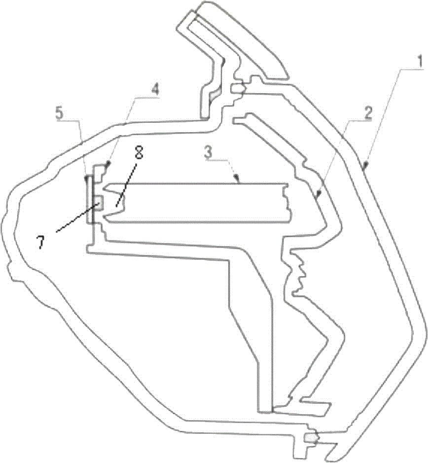
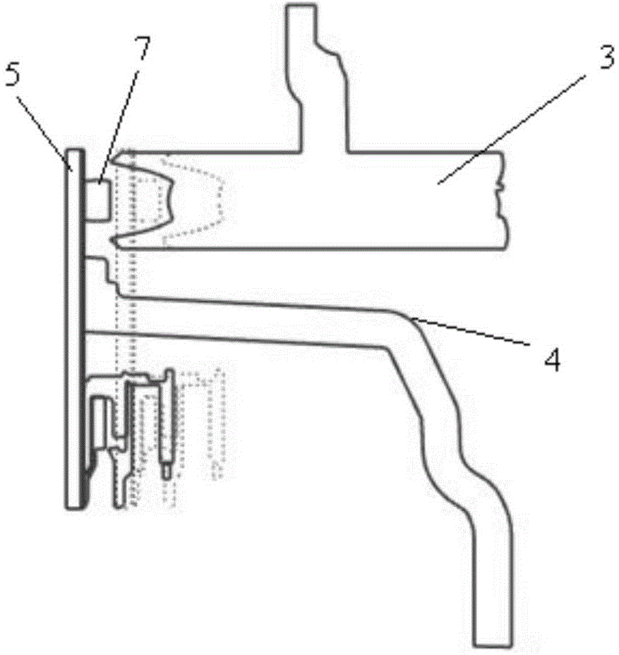
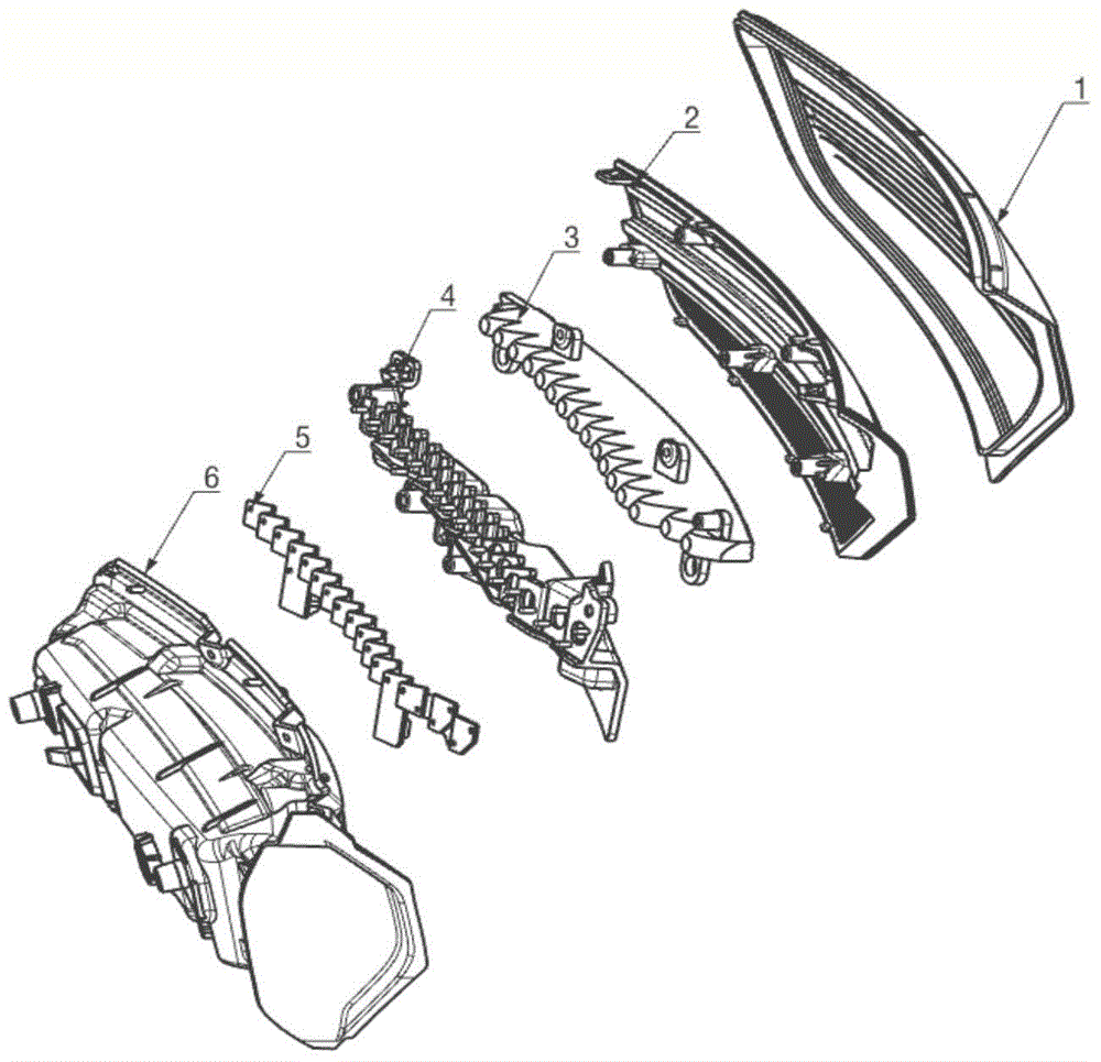
[0027] Such as figure 1 As shown, the functional module of the automobile tail light of the present invention includes several LED light sources 7, transparent light guide plates 3, LED mounting brackets 4 and LED circuit boards 5, and the transparent light guide plates 3 are fixed on the LED mounting brackets 4 Above, one end of the transparent light guide plate 3 has a sawtooth structure, and the other end is provided with a groove 8 , and each groove is provided with an LED light source 7 fixed on the LED circuit board 5 . The LED light source is arranged in each groove, so that the LED light source can be hidden in all directions, and at the same time, the light utilization rate is high, the luminous purity is high, and the color is bright.

[0028] The transparent light guide plate 3 is located on the front of the LED installati...


PUM


Abstract

The invention relates to an automobile tail lamp functional module and an LED circuit board installation method thereof. The functional module comprises a plurality of LED light sources, a transparent light guide plate, an LED installation support and an LED circuit board. The transparent light guide plate is fixed to the LED installation support. One end of the transparent light guide plate is of a sawtooth structure, and grooves are formed in the other end of the transparent light guide plate. Each groove is internally provided with one LED light source. The transparent light guide plate is located on the front face of the LED installation support. The LED circuit board is located on the back face of the LED installation support and used for adding the thickness of the LED circuit board on the depth of the grooves in the transparent light guide plate. Through holes are formed in the portions, corresponding to the LED light sources fixed to the LED circuit board, of the LED installation support. The LED light sources penetrate through the through holes to be correspondingly arranged inside the grooves in the transparent light guide plate. According to the automobile tail lamp functional module, LED installation and lighting effect uniformity and continuity are better facilitated.

Description

technical field [0001] The invention relates to the technical field of automobile lamps, in particular to a functional module of an automobile tail lamp and an installation method for an LED circuit board thereof. Background technique [0002] With the continuous improvement of LED application technology and the gradual decline of cost, LED is getting closer and closer to the beauty of large-scale application in mass-produced vehicle systems after the preliminary conception stage of technical verification and concept car display in automotive electronics in recent years. prospect. The use of LEDs in automotive lights is currently mainly focused on the use of taillights and trunk lights. [0003] The conventional LED circuit board position design for automobile tail lights is: the LED circuit board is installed between the light guide plate and the LED mounting bracket, and is located on the front of the LED mounting bracket. However, this conventional design needs to meet:...

Claims


Application Information

Patent Timeline
Patent Type & Authority Applications(China)
IPC IPC(8): F21S8/10F21V19/00F21V17/10F21W101/02F21W101/14F21Y101/02F21W107/10
CPCF21S43/14F21S43/195F21V17/101F21V19/003F21W2103/00F21W2107/10
Inventor 刘春霞
Owner HASCO VISION TECHNOLOGY CO LTD
Why Eureka
Try Eureka