Clutch driving device of electronic lock

A driving device and electronic lock technology, applied in the field of locks, can solve the problems of affecting normal use, unable to control the lock body to open the door leaf, unable to control the handle in linkage, etc., and achieve the effect of simple structure

Inactive Publication Date: 2015-09-23
白炳武
View PDF5 Cites 4 Cited by
  • Summary
  • Abstract
  • Description
  • Claims
  • Application Information

AI Technical Summary

Problems solved by technology

[0003] The traditional electric lock control panel is equipped with a handle, an electric controller with a password button or a fingerprint verifier, a lock body and a clutch assembly, wherein the clutch assembly includes a lock body linkage shaft linked with the lock body and a handle Linked handle linkage shaft, the lock body linkage shaft is provided with a rotating chamber for the handle linkage shaft to be inserted and rotated coaxially, the wall of the rotating chamber is provided with a clutch lever that can automatically reset to the outside, and the handle linkage shaft is arranged radially There is a clutch groove matched with the clutch lever. One end of the clutch lever faces the inner side of the rotating chamber as the mating end with the clutch groove, and the other end extends out of the rotating chamber as the control end. When the correct password or fingerprint is input, the electric controller pushes the clutch lever The control end of the control end makes the matching end extend into the clutch groove to form the linkage between the handle linkage shaft and the lock body linkage shaft. The handle controls the lock body to realize the purpose of opening the door leaf, and when there is no or wrong password or fingerprint input, the electric controller will not Action, the mating end of the clutch lever is far away from the clutch groove, and the handle can't control the lock body to open the door when the handle is idling
After twisting the handle for a long time, the position of the clutch groove of the handle linkage shaft and the mating end of the clutch lever will be slightly shifted, so that the electric controller cannot push the clutch lever, that is, the handle cannot pass through the lock body linkage axis and the handle linkage axis. The linkage control handle greatly affects the normal use

Method used


Image

  • Clutch driving device of electronic lock
  • Clutch driving device of electronic lock
  • Clutch driving device of electronic lock

Examples


Embodiment Construction

[0019] The present invention will be further described below with reference to the accompanying drawings.

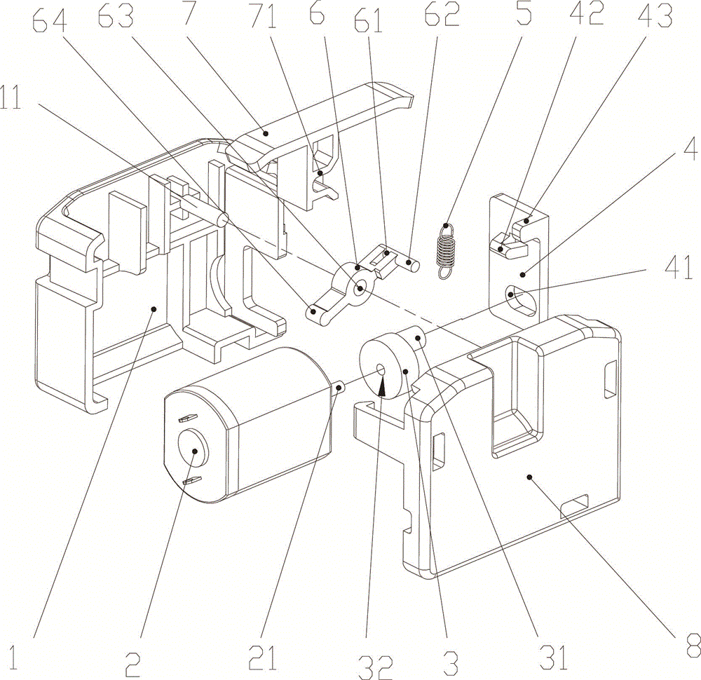
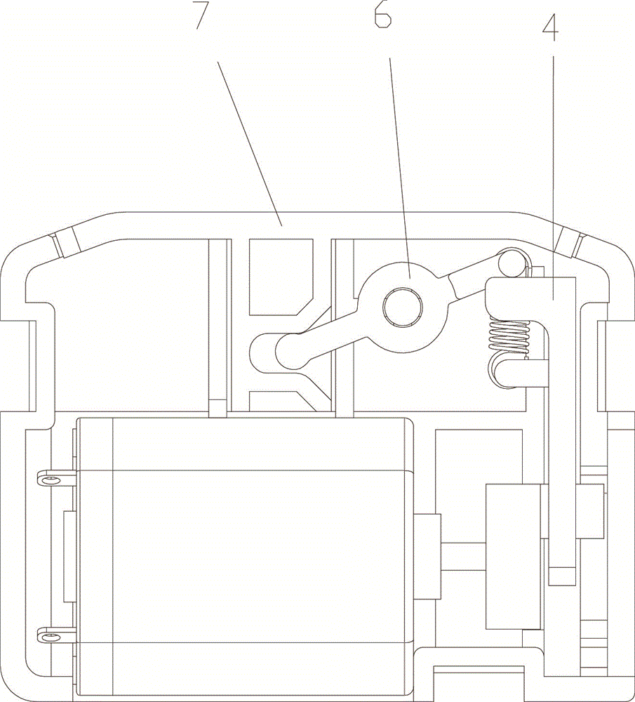
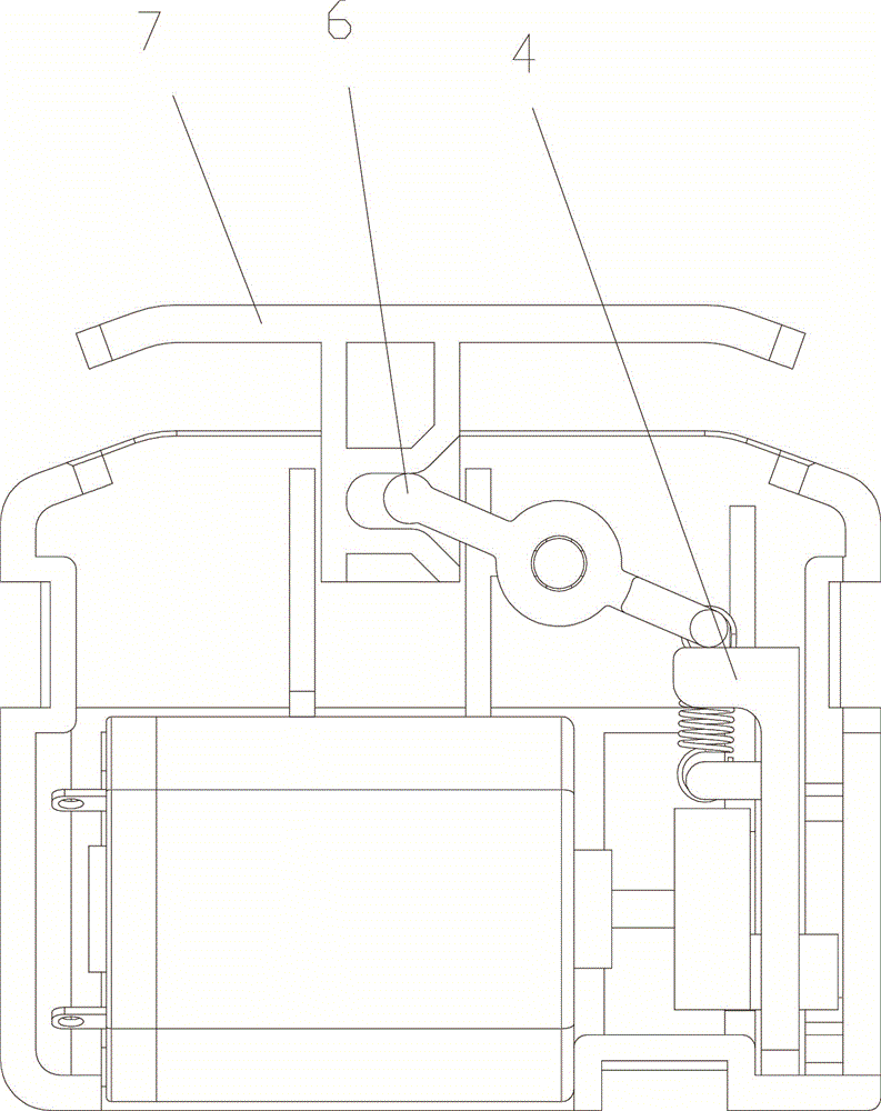
[0020] Such as Figure 1-4 As shown, an electronic lock clutch driving device includes a cam 3, and the cam 3 is connected with a push rod 4 to drive it to move up and down. The driving rod 6 is arranged on a fixed rotating shaft 11 and can rotate around it. The driving rod 6 is driven by the push rod 4 to move around the rotating shaft 11 to eject or retract the push plate 7 connected with the driving rod 6 . The cam 3 is provided with a push-out portion 31 connected to the push rod 4, and the push rod 4 is provided with a groove 41 for accommodating the push-out portion 31, and the push-out portion 31 acts in the groove 41 so that Push rod 4 moves up and down. The push rod 4 is provided with a first extension spring hook 42, and the shift lever 6 is provided with a second extension spring hook 61, and the two ends of the extension spring 5 are connected with the firs...


PUM


Abstract

The invention discloses a clutch driving device of an electronic lock. The clutch driving device comprises a cam, wherein the cam is connected with a push rod and used for driving the push rod to vertically move; the push rod is connected with a lifting lever through a tensile spring, the lifting lever is arranged on a fixed rotary shaft and rotates around it; the lifting lever is moved around the rotary shaft by the push rod so as to pop out or withdraw the push plate connected with the lifting lever. The clutch driving device is simple in structure; through the rotation of the cam, the vertical movement of the push rod is controlled, and the push rod is further connected with the lifting lever through the tensile spring; the lifting lever is moved around the rotary shaft by the push rod so as to pop out or withdraw the push plate connected with the lifting lever, thus the clutch is realized; besides, the action of the tensile spring cannot damage the cam when the external force pushes the push plate to withdraw.

Description

technical field [0001] The invention relates to a lock, in particular to a clutch driving device for an electronic lock. Background technique [0002] In daily life, it is often seen that electric control locks such as code locks and fingerprint locks are used in various occasions, especially public places such as hotels and shopping malls, due to the convenience of not carrying keys and the high security of passwords and fingerprints , deeply loved by the people. [0003] The traditional electric lock control panel is equipped with a handle, an electric controller with a password button or a fingerprint verifier, a lock body and a clutch assembly, wherein the clutch assembly includes a lock body linkage shaft linked with the lock body and a handle Linked handle linkage shaft, the lock body linkage shaft is provided with a rotating chamber for the handle linkage shaft to be inserted and rotated coaxially, the wall of the rotating chamber is provided with a clutch lever that...

Claims


Application Information

Patent Timeline
IPC IPC(8): E05B47/06
Inventor 白炳武
Owner 白炳武
Why Eureka
Try Eureka