
Stand base for microscopes

一种支撑座、显微镜的技术,应用在显微镜、应用、支承机器等方向,能够解决重量重心改变等问题,达到实现使用寿命、长使用寿命、不易故障的效果

Active Publication Date: 2015-09-23
LEICA MICROSYSTEMS (SCHWEIZ) AG
View PDF10 Cites 2 Cited by
  • Summary
  • Abstract
  • Description
  • Claims
  • Application Information

AI Technical Summary

Problems solved by technology

[0003] Another problem that occurs with the support part of the surgical microscope is that its weight and / or center of gravity change depending on the position and number of additional parts
The disadvantage of this braking system is that several pedals have to be pressed in order to fasten safely

Method used


Image

  • Stand base for microscopes
  • Stand base for microscopes
  • Stand base for microscopes

Examples


Embodiment Construction

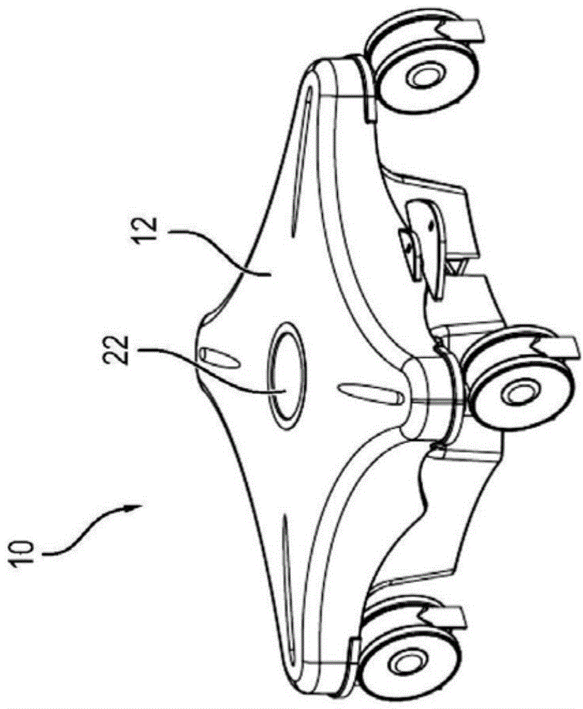
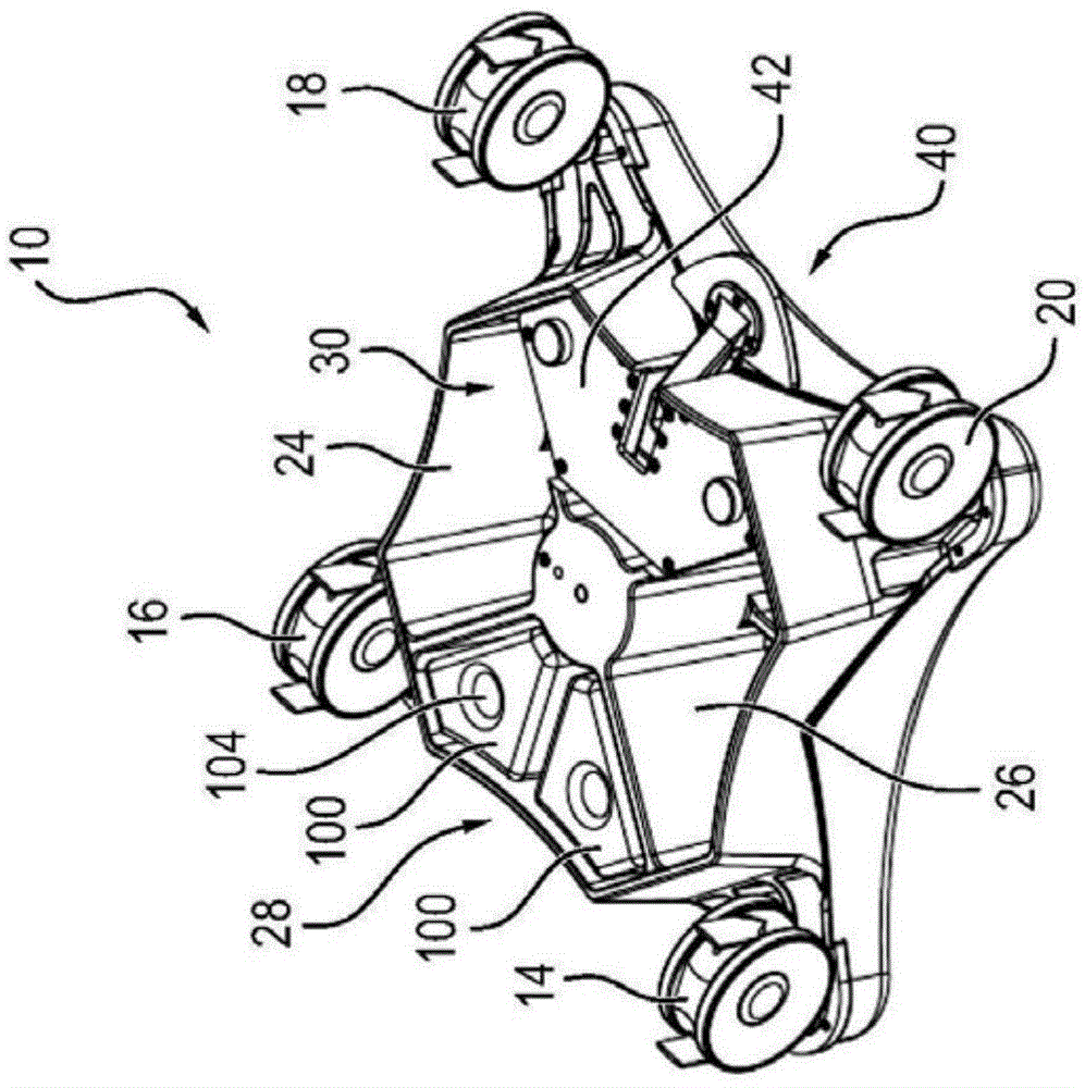
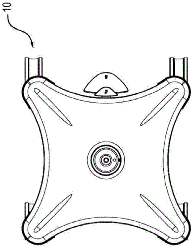
[0048] figure 1 is a schematic perspective view of the support base 10 looking towards the upper side of the support base 10 . figure 2 It is another schematic diagram of the support base 10 , where the line of sight is directed downward. image 3 based on figure 1 and figure 2 The top view of the support base, Figure 4 based on figure 1 and figure 2 The side view of the support seat, and Figure 5 based on figure 1 and figure 2 The bottom view of the support base.

[0049] The support base 10 includes a support base body 12 on which four rollers 14 to 20 are installed, and the support base 10 is displaceably installed on the floor through the rollers 14 to 20 . In the exemplary embodiment shown, the rollers 14 to 20 are double rollers which allow a particularly simple displacement without energy consumption. In an alternative embodiment, a single roller can also be used. The support base 10 may also include fewer than four rollers 14 to 20 (for example three r...


PUM


Abstract

The invention relates to a stand base (10) for microscopes, which encompasses a stand base body (12) on which multiple rollers (14 to 20) for displacing the stand base (10) are fastened. The stand base (10) furthermore has a braking system (40) to prevent displacement of the stand base (10), the braking system encompassing at least two braking feet (44, 46).

Description

technical field [0001] The invention relates to a support base for a microscope, especially an operating microscope. The support base includes a support base body, on which a plurality of rollers are fastened, and is used for displaceably supporting the support base on the floor. The support base also has a braking system for preventing displacement of the support base, the braking system comprising at least two brake feet which, in the braking position, press against the floor and thus prevent or at least hinder displacement of the support base. position, and in the released position, the brake foot enables the support to be displaced. Background technique [0002] Surgical microscopes are usually heavy, so their supports include rollers so that the surgical microscope can be easily moved from one position to another without lifting the surgical microscope. Conversely, however, it is required that the operating microscope does not move unintentionally during the operation,...

Claims


Application Information

Patent Timeline
Patent Type & Authority Applications(China)
IPC IPC(8): F16M11/20G02B21/24A61B19/00
CPCB60B33/0089B60T1/14F16M11/42B60B33/0042B60B33/0078B60T3/00
Inventor 马可·舒茨拉尔夫·柯尔柏
Owner LEICA MICROSYSTEMS (SCHWEIZ) AG
Learn More