
H-bridge tandem-type STATCOM DC side power supply system

A power supply system, DC side technology, applied in flexible AC power transmission system, control/regulation system, DC power input conversion to DC power output, etc., can solve problems affecting the quality of output voltage and current waveforms

Active Publication Date: 2015-10-21
XIAN UNIV OF TECH
View PDF2 Cites 1 Cited by
  • Summary
  • Abstract
  • Description
  • Claims
  • Application Information

AI Technical Summary

Problems solved by technology

[0004] The purpose of the present invention is to provide a kind of H-bridge series STATCOM DC side power supply system, which solves the problem that the H-bridge unit of the H-bridge series STATCOM in the prior art can affect the quality of the output voltage and current waveform

Method used


Image

  • H-bridge tandem-type STATCOM DC side power supply system
  • H-bridge tandem-type STATCOM DC side power supply system
  • H-bridge tandem-type STATCOM DC side power supply system

Examples


Embodiment

[0104] The calculation of relevant parameters of an H-bridge series STATCOM DC side power supply system is as follows:

[0105] Step 1. First, according to the system line voltage U of the H-bridge series STATCOM DC side power supply system ab =10kV and load maximum reactive power Q Lmax =10MVar, to determine the rated current I of the H-bridge series STATCOM DC side power supply system S , rated current I S The selection of is according to the formula:

[0106] I s = Q L max / 3 U a b / 3 = 577 A - - - ( 1 )

[0107] Step 2. Accordin...


PUM


Abstract

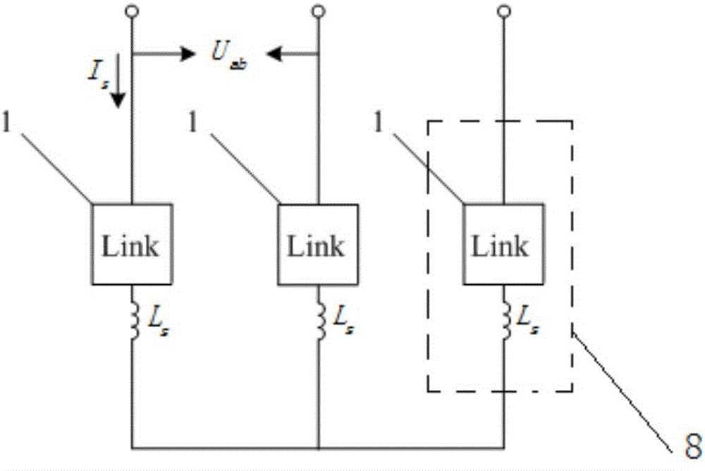
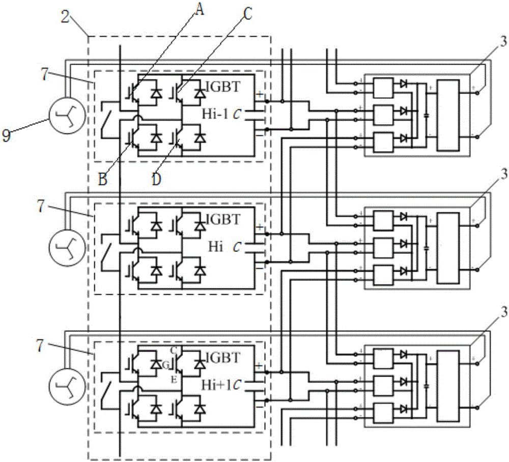
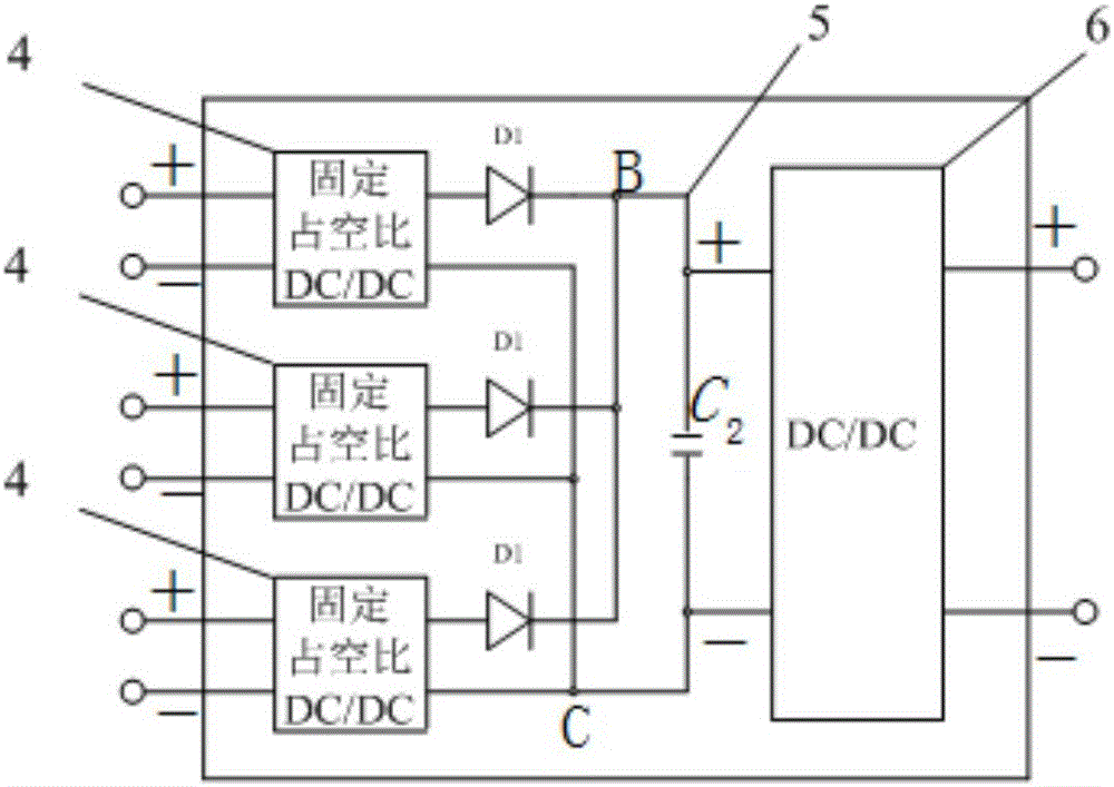
The invention discloses an H-bridge tandem-type STATCOM DC side power supply system, and the system comprises Link module strings which are respectively connected to three phase lines. Each Link module string comprises a Link module and an inductor Ls, wherein three inductors Ls are connected with the unconnected ends of three Link modules. The invention also discloses the calculation of related parameters of the system. The system solves a problem that the energy extraction of an H-bridge unit of an H-bridge tandem-type STATCOM in the prior art affects the waveform quality of output voltage and current.

Description

technical field [0001] The invention belongs to the technical field of reactive power compensation, and in particular relates to an H-bridge series STATCOM DC side power supply system. Background technique [0002] With the continuous increase of the grid voltage connected to the H-bridge series STATCOM, the low-cost and high-reliability power supply of the H-bridge unit has become a great challenge in the design of the H-bridge unit of the H-bridge series STATCOM. Using the switching power supply to directly obtain energy from the H-bridge DC capacitor can reduce the voltage insulation requirements of the switching power supply, thereby reducing the volume and cost of the energy harvesting power supply. [0003] The H-bridge unit energy harvesting technology of the existing H-bridge series STATCOM is mainly divided into: low-voltage AC energy harvesting and high-voltage DC energy harvesting. Low-voltage AC energy harvesting technology uses a transformer with high insulatio...

Claims


Application Information

Patent Timeline
IPC IPC(8): H02J3/36H02J3/18H02M3/335
CPCY02E40/10Y02E60/60
Inventor 杨波张静刚曾光张晓滨杨勇粟忠来
Owner XIAN UNIV OF TECH
Learn More