
Brake handle adjustment structure

A technology for adjusting structure and handlebars, applied to bicycle accessories, bicycle brakes, bicycle control systems, etc., can solve problems such as rust, no effective shielding components, affecting the appearance and smoothness of the handle, and achieve the effect of easy grip distance

Active Publication Date: 2017-10-03
TIEN HSIN INDS
View PDF6 Cites 0 Cited by
  • Summary
  • Abstract
  • Description
  • Claims
  • Application Information

AI Technical Summary

Problems solved by technology

[0004] However, although the above-mentioned brake handle adjustment structure can provide the adjustment of the grip distance, the housing must have an opening for easy operation. In addition to affecting the appearance and smoothness of the grip, the opening is also prone to water seepage due to no effective shielding. corrosion of components

Method used


Image

  • Brake handle adjustment structure
  • Brake handle adjustment structure
  • Brake handle adjustment structure

Examples


Embodiment Construction

[0040] In order to clearly illustrate a brake handle grip distance adjustment structure of the present invention, a preferred embodiment will be given and described in detail below with reference to the techniques, means and achieved effects.

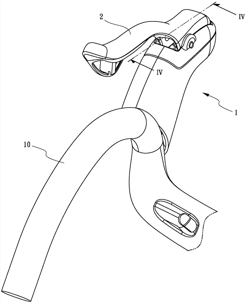
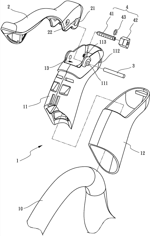
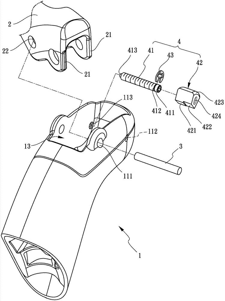
[0041] See first Figure 1 to Figure 3 As shown, a brake handle grip adjustment structure of the present invention is disclosed, which includes a handle base 1 , a brake handle 2 and an adjustment assembly 4 . The handle base 1 is disposed on the bicycle handle 10 and has an accommodating groove 13 inside. The brake handle 2 is pivotally disposed in the accommodating groove 13 and protrudes from two sides of the top end of the brake handle 2 respectively. A pivot 3 passes through the brake handle 2 and the handle base 1 so that the brake handle 2 and the handle base 1 can pivot relative to each other. The adjustment assembly 4 is arranged in the accommodation groove 13 and has a screw rod 41 and an adjustment member 42 screwed on the ...


PUM


Abstract

The invention discloses a brake handle grip width adjusting structure which comprises a handle base, a brake handle, a pivot and an adjusting assembly. A containing groove is arranged inside the handle base. The brake handle is arranged in the containing groove. The brake handle stretches out in a protruding manner to form two flanges. The pivot is provided with the brake handle and the handle base in a penetrating manner, so that the brake handle and the handle base pivot with the pivot as an axis. The adjusting assembly is arranged inside the containing groove and provided with a screw rod and an adjusting piece. The adjusting piece is movably arranged on the screw rod. When the screw rod is rotated, the adjusting piece moves relative to the screw rod to selectively abut against either flange of the brake handle or to be located between the two flanges, and therefore the grip width of the brake handle is adjusted.

Description

technical field [0001] The invention relates to a structure for adjusting the grip distance of a brake handle, in particular to an adjustment structure for the grip distance of a brake handle of a road vehicle, so as to easily adjust the distance between the brake handle and the handle of a bicycle. Background technique [0002] Bicycle brake handles are used to control the braking system to achieve the effect of stopping the brakes. However, the grip distance between the known brake handles and the bicycle handle is usually fixed, but for riders with smaller hands, because of the distance from the brake handle Too far to reach comfortably, especially for the bend-type handlebars of road bikes. The brake handle is held too far away, and it is easy to increase the danger of riding. [0003] In order to solve the above-mentioned problems, please refer to Taiwan Patent Publication No. I356025 for the manually configurable and range-adjusting technology of the handle-mounted lev...

Claims


Application Information

Patent Timeline
Patent Type & Authority Patents(China)
IPC IPC(8): B62L3/02B62K23/06
CPCB62K23/06B62L3/026
Inventor 邱龙斐
Owner TIEN HSIN INDS
Learn More