Water pumping method of water pushing pipes and efficient liquid pump using method

A technology for liquid pumps and water pipes, which is applied to pumps, machines/engines, mechanical equipment, etc., and can solve the problems of low pressure of the pumped liquid flow, waste of liquid flow kinetic energy, and increased energy consumption.

Inactive Publication Date: 2015-10-28
吴新保
View PDF5 Cites 2 Cited by
  • Summary
  • Abstract
  • Description
  • Claims
  • Application Information

AI Technical Summary

Problems solved by technology

The impeller type uses the principle of centrifugal force to throw water to the outside of the impeller, and then forms a high pressure there to press the water out of the pump. The center part of the impeller uses the low pressure formed by centrifugal force to suck in the water outside the pump, and so on. The propeller type also uses the blades to quickly agitate, shear and push the water flow. Every drop of water passing through the pump is from the smooth flow of the inlet pipe, to the complex centrifugal torrent or agitation and extrusion, and then to the smooth flow of the outlet pipe. During this process, there may be several small eddies of water flow mixed in, and the pressure of the water flow changes drastically; the piston type uses the reciprocating movement of the piston to continuously change the capacity of the liquid in the cylinder to absorb and push water, and the static cylinder. When the liquid inlet valve is closed, the liquid flow can only stop moving, wasting the kinetic energy of the continuous flow of liquid
These all increase energy consumption and reduce the energy utilization efficiency of the pump; the structure of the extrusion liquid pump is somewhat complicated, and it is difficult to reduce the diameter of the pump to be used in a deep well; there is also an inertia pump, which uses a pipeline with a one-way valve Reciprocating motion pushes the fluid to flow continuously in one direction, but the speed of the continuous flow of the liquid varies greatly, which cannot achieve efficient pumping, and the pressure of the pumped liquid flow is also small

Method used


Image

  • Water pumping method of water pushing pipes and efficient liquid pump using method
  • Water pumping method of water pushing pipes and efficient liquid pump using method
  • Water pumping method of water pushing pipes and efficient liquid pump using method

Examples


Embodiment 2

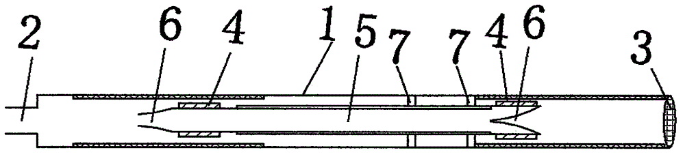
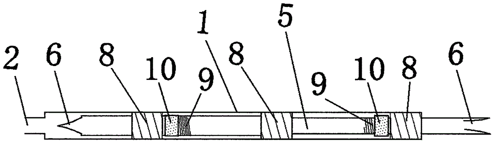
[0008] Such as image 3 , Figure 4 Put into three sets of electromagnets 8 in the pump body 1 of all, two are fixed with iron block 10, and push away the water pipe 5 of spring 9, wherein the internal diameter of one pushes away water pipe 5 is slightly larger than the outer diameter of another, two The push water pipes 5 are set together one after the other, and are attracted by electromagnetic force to reciprocate in opposite directions. When the two push water pipes 5 are pushed relative to each other, as Figure 4 As shown, when the middle electromagnetic 8 is energized first to generate electromagnetic force to attract the two water push pipes 5 with iron blocks 10 at the same time, the one-way valve 6 of the forward push water pipe 5 near the water outlet 2 is opened, and the one-way valve of the rear push water pipe 5 is opened. 6 is closed, the water is pushed out of the water outlet 2 by the water pipe 5, and then the contact breaks the circuit, such as image 3 As...

Embodiment 3

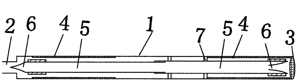
[0010] Figure 5 , Image 6 As shown, the power machine using the common shaft output power 13 uses the crankshaft 11 to cooperate with the connecting rod 12 or other methods to drive the two water pushing pipes 5 to reciprocate in opposite directions respectively. The upper end of the pump body 1 is the water outlet 2 , the middle of the water sealing ring 7 in the pump body 1 is two water pushing pipes 5, and the water pushing pipes 5 have at least one one-way valve 6 respectively, such as Figure 5 , when the crankshaft 11 rotates and the connecting rod 12 drives the two water push pipes 5 to push relative to each other, the one-way valve 6 of the forward push water pipe 5 near the water outlet 2 is opened, and the one-way valve 6 of the rear push water pipe 5 is closed, and the water is pushed back by the water pipe 5 to push out the water outlet 2, when the crankshaft 11 continues to rotate, the connecting rod 12 drives the two water push pipes 5 to push in the opposite ...


PUM


Abstract

The invention discloses a water pumping method of water pushing pipes and a liquid pump using the method. The problem of extra power consumption and the problem that a piston pump affects the continuity of liquid flow due to the fact that the direction and the speed of the liquid flow pumped by a centrifugal liquid pump are changed multiple times are solved. According to the method, two pipelines, i.e., the water pushing pipes with one-way valves are used for making reciprocating motion in opposite directions, so that one-way pushing is conducted on the liquid flow; the liquid flow flows in a pump body smoothly, continuously and evenly; the structure is simple; and efficiency is high. A plurality of combinations are applied in a composite mode, a liquid inlet of the previous combination and a liquid outlet of the next combination are connected together, the combinations are connected in series for application, and the method is suitable for a deep oil well pump, a high lift pump, a high pressure pump and the like.

Description

Technical field [0001] The invention belongs to the field of liquid pumps, and specifically relates to a method for pushing water pipes to pump water and a novel high-efficiency liquid pump using the method. technical background [0002] Existing known liquid pumps, such as lift pumps, deep well pumps and booster pumps, generally have impeller type, propeller type, reciprocating type, and extrusion type. The impeller type uses the principle of centrifugal force to throw water to the outside of the impeller, and then forms a high pressure there to press the water out of the pump. The center part of the impeller uses the low pressure formed by centrifugal force to suck in the water outside the pump, and so on. The propeller type also uses the blades to quickly agitate, shear and push the water flow. Every drop of water passing through the pump is from the smooth flow of the inlet pipe, to the complex centrifugal torrent or agitation and extrusion, and then to the smooth flow o...

Claims


Application Information

Patent Timeline
IPC IPC(8): F04F7/00
CPCF04F7/00
Inventor 吴新保
Owner 吴新保
Why Eureka
Try Eureka