Tri-band antenna based on CSRR and LHTL

A technology for antennas and small antennas, which is applied in the connection of antennas, antenna grounding switch structures, and devices that enable antennas to work in different bands at the same time. It can solve the problems of narrow impedance bandwidth of multi-frequency antennas and achieve good radiation characteristics and wide impedance bandwidth. Effect

Active Publication Date: 2015-10-28
HARBIN INST OF TECH
View PDF4 Cites 6 Cited by
  • Summary
  • Abstract
  • Description
  • Claims
  • Application Information

AI Technical Summary

Problems solved by technology

[0004] The purpose of the present invention is to solve the problem that the impedance bandwidth of existing multi-frequency antennas is generally narrow, and the present invention provides a tri-frequency antenna based on CSRR and LHTL

Method used


Image

  • Tri-band antenna based on CSRR and LHTL
  • Tri-band antenna based on CSRR and LHTL
  • Tri-band antenna based on CSRR and LHTL

Examples


specific Embodiment approach 1

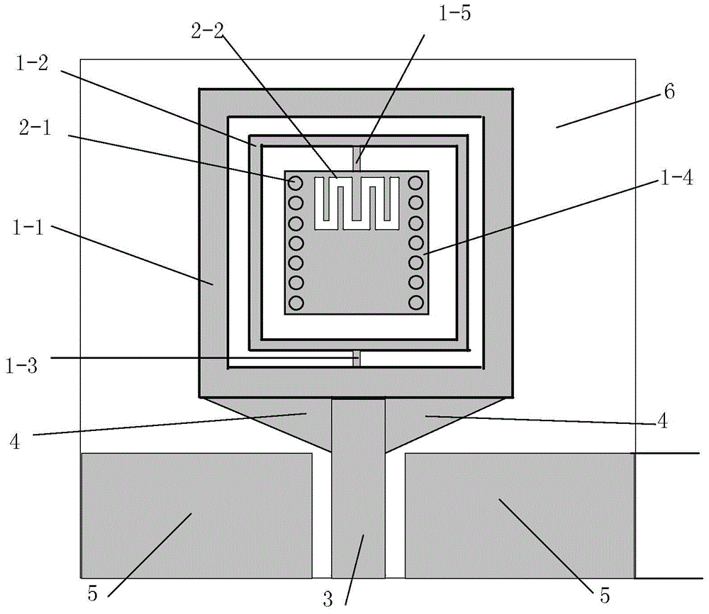
[0043] Specific implementation mode one: combine figure 1 Describe this embodiment, the tri-band antenna based on CSRR and LHTL described in this embodiment, the antenna includes a complementary split ring resonator CSRR (Complementary Split Ring Resonator), a left-handed transmission line LHTL (Left Handed Transmission Line), a coplanar waveguide CPW3, two triangular impedance matching units 4, two virtual floors 5 and a dielectric board 6;

[0044] Complementary split ring resonator CSRR, left-handed transmission line LHTL, coplanar waveguide CPW3, two triangular impedance matching units 4 and two virtual floors 5 are all coated on the upper surface of the dielectric board 6; the antenna is centered on the midline of the dielectric board 6 Axisymmetric structure;

[0045] The complementary split ring resonator CSRR includes an outer square metal ring 1-1, an inner square metal ring 1-2, a first metal rod 1-3, a first square metal sheet 1-4 and a second metal rod 1-5;

[00...

specific Embodiment approach 2

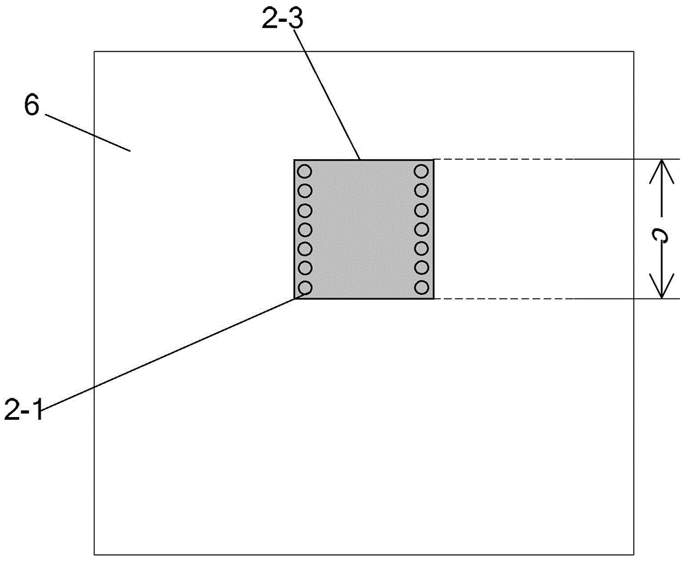
[0053] Specific implementation mode two: combination Figure 4 to Figure 14 Describe this embodiment. This embodiment is a further limitation of the tri-band antenna based on CSRR and LHTL described in Embodiment 1. The left-hand transmission line LHTL includes interdigitated capacitors 2-1 and 14 metal rods 2-2 and The second square metal sheet 2-3;

[0054] The second square metal sheet 2-3 is arranged on the lower surface of the dielectric plate 6, the position of the second square metal sheet 2-3 on the dielectric plate 6 corresponds to the position of the first square metal sheet 1-4, and the shape and size are the same ;

[0055] The 14 metal rods are divided into two groups, and the two groups of metal rods are arranged in a row at equal intervals, respectively inserted into both sides of the first square metal sheet 1-4, and pass through the first square metal sheet 1-4, and the interdigitated capacitor 2-1 is arranged on the upper surface of the first square metal s...

specific Embodiment approach 3

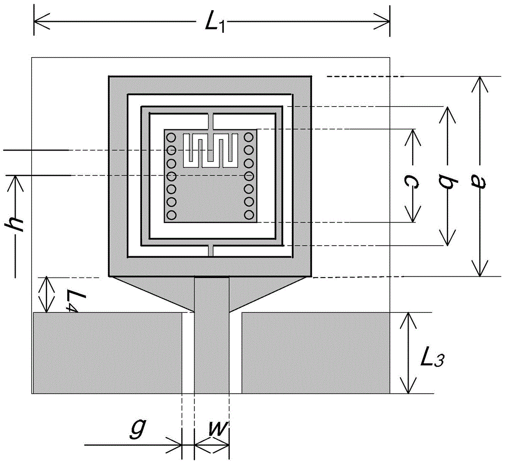
[0063] Specific implementation mode three: combination image 3 and Figure 4 Describe this embodiment. This embodiment is a further limitation of the tri-band antenna based on CSRR and LHTL described in the second specific embodiment. In this embodiment, the side length a of the outer square metal ring 1-1 is 11mm , with a width of 1mm;

[0064] The side length b of the inner square metal ring 1-2 is 7.6mm, and the width is 0.3mm;

[0065] The side length c of the square metal sheet 1-4 is 5.6mm.

[0066] The finger width p=0.45mm of the interdigitated capacitance, length L 5 =2.6mm, the width of the gap between two adjacent fingers q=0.25mm; the diameter D=0.4mm of the metal rod; the cross-section of the dielectric plate 6 is a square, and its side length L 1 =20mm, dielectric constant ε r =4.4; the length of the triangular impedance matching unit 4 is L 4 =1.77mm; the width L of the virtual floor 5 3 = 5.56mm; the width w of the planar waveguide CPW 3 = 1.48mm,

[0...


PUM


Abstract

The invention discloses a tri-band antenna based on CSRR and LHTL, which belongs to the technical field of multi-frequency antennas based on a metamaterial structure. The problem of universally narrow impedance bandwidth of the existing multi-frequency antenna is solved. The antenna is in an axial symmetry structure by taking the center line of a dielectric plate of the axis. A complementary split ring resonator CSRR, a left hand transmission line LHTL, a coplanar waveguide CPW, two triangle impedance matching units and two virtual floors cover the upper surface of the dielectric plate. The complementary split ring resonator CSRR structure realizes first two work bands of the antenna, and the antenna works in a dipole antenna mode. The left hand transmission line LHTL realizes a third additional work band. The coplanar waveguide CPW is connected with the complementary split ring resonator CSRR. Two triangle impedance matching units are respectively inserted into a space between the left side of the coplanar waveguide CPW and the complementary split ring resonator CSRR and a space between the right side of the coplanar waveguide CPW and the complementary split ring resonator CSRR. The tri-band antenna is applied to indoor communications.

Description

technical field [0001] The invention relates to a triple-frequency multi-mode antenna based on CSRR and LHTL, and belongs to the technical field of multi-frequency antennas based on a metamaterial structure. Background technique [0002] With the rapid development of modern wireless indoor communication technology, corresponding antenna systems have emerged as the times require. The traditional single-frequency antenna can no longer meet the current communication requirements, so a very important issue is how to use one antenna to receive and transmit multiple signals of different frequencies. Multi-frequency antennas emerged at the historic moment and received more and more attention in the scientific community. Multi-band antennas are widely used in indoor communication due to their advantages of flexibility, small footprint, portability, low cost and wide frequency band. [0003] In 2012, S.X.Ta et al realized a dual-frequency antenna by using crossed asymmetric oscilla...

Claims


Application Information

Patent Timeline
Patent Type & Authority Applications(China)
IPC IPC(8): H01Q5/20H01Q1/50H01Q1/38
Inventor 祁嘉然刘畅肖姗姗邱景辉
Owner HARBIN INST OF TECH
Why Eureka
Try Eureka