Broadband millimeter wave antenna

A millimeter-wave antenna and broadband technology, applied in the field of broadband millimeter-wave antennas, can solve the problems of low radiation efficiency in the millimeter-wave frequency band, difficult processing of horn antennas, and complex feeding structure, and achieve a good radiation pattern and a good standing wave. The effect of the simple structure of the antenna and the

Active Publication Date: 2016-12-14
SOUTHEAST UNIV
View PDF4 Cites 6 Cited by
  • Summary
  • Abstract
  • Description
  • Claims
  • Application Information

AI Technical Summary

Problems solved by technology

However, due to the very short wavelength of the signal in the millimeter wave frequency band, it poses great challenges to the processing, interconnection, and massive MIMO array application of the antenna
Although planar printed antennas such as microstrip patch antennas are easy to process, they tend to have narrow bandwidths and low radiation efficiency in the millimeter wave band
Although the horn antenna has superior performance in the millimeter-wave frequency band, the traditional high-frequency horn antenna is difficult to process, high in cost, large in size, complex in feeding structure, and difficult to integrate with planar circuits or perform compact array applications.

Method used


Image

  • Broadband millimeter wave antenna
  • Broadband millimeter wave antenna
  • Broadband millimeter wave antenna

Examples


Embodiment Construction

[0023] The present invention will be further described below in conjunction with the accompanying drawings.

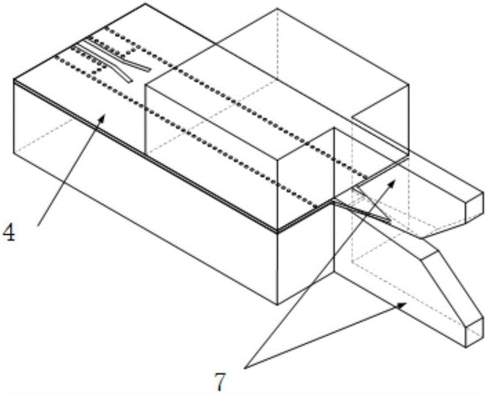
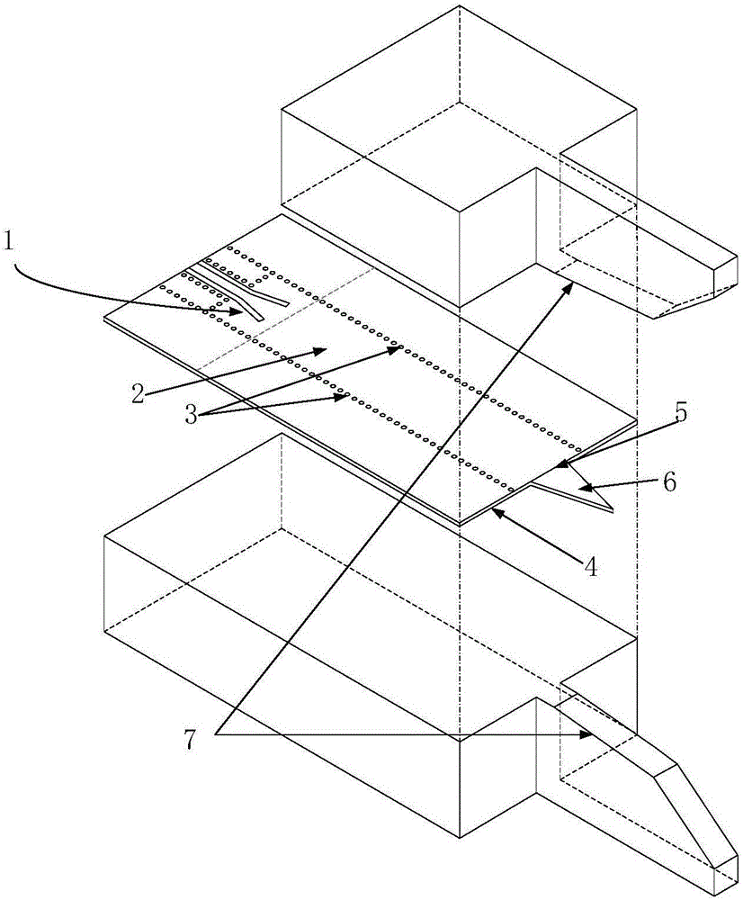
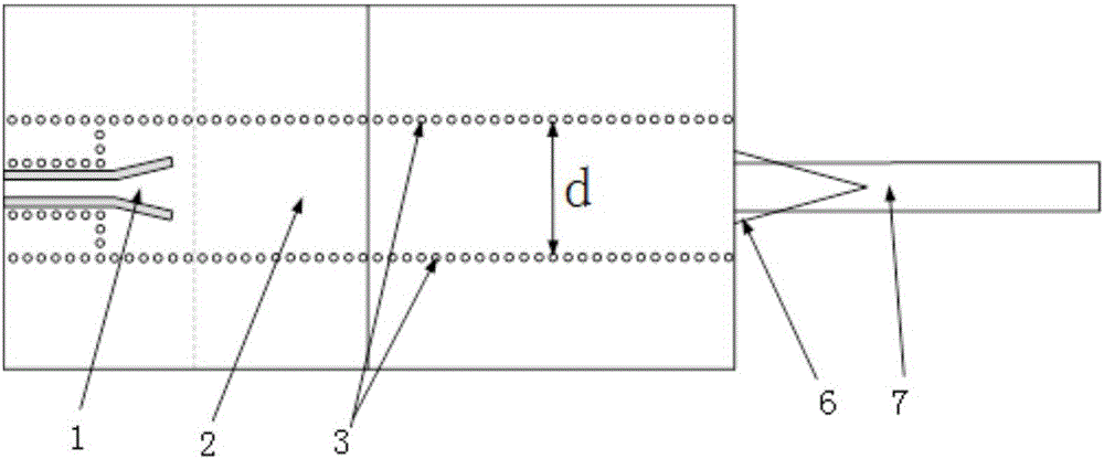
[0024] Such as Figures 1 to 4 Shown is the structure diagram of this embodiment, it is a kind of broadband millimeter-wave antenna, comprises upper and lower metal blocks and the dielectric substrate 4 in the middle, the screw hole that can be machined on the metal block that metal arm 7 is carried, can be screwed The upper and lower metal blocks are tightly pressed against the dielectric substrate 4 in the middle. The upper and lower metal blocks can be designed as a structure with a short top and a long bottom. One end of the upper and lower metal blocks is aligned, and the part of the lower metal block longer than the upper metal block can be integrated with the base plate mechanism of the transceiver during use to realize integration.

[0025] A metal arm 7 extends from one side of the upper and lower metal blocks respectively; the two metal arms 7 are mirror ima...


PUM


Abstract

Provided is a broadband millimeter wave antenna. The antenna comprises an upper rectangular metal block, a lower rectangular metal block, and an intermediate dielectric substrate, one sides of the upper rectangular metal block and the lower rectangular metal block are respectively provided with a metal arm in an extended manner, the two metal arms are in mirror symmetry with respect to the dielectric substrate, the distances between two opposite surfaces of the metal arms are equal, the distances between two surfaces, which are face to face, of the metal arms are gradually increased along the length direction, a V-shaped radiation opening is formed, the end of the radiation opening forms a horn-shaped mouth portion, one end, with large diameter, of the mouth portion, is arranged towards the outside of the radiation opening, the upper surface and the lower surface of the dielectric substrate are metal surfaces, the dielectric substrate is provided with a switching circuit and a substrate integrated waveguide along the length direction, the switching circuit is arranged from a microstrip line to the substrate integrated waveguide, an output end of the substrate integrated waveguide is provided with a dielectric plate in an extended manner, the width of the dielectric plate is gradually reduced along the length direction, and the dielectric plate stretches into the radiation opening. The antenna is advantaged by wide bandwidth, low cost, small size, simple and compact structure, and easy integration and array organization.

Description

technical field [0001] The invention relates to the technical field of antennas, in particular to a broadband millimeter-wave antenna. The antenna works in the millimeter-wave frequency band and has the characteristics of low complexity and easy integration with planar circuits. Background technique [0002] Antennas are one of the key components of wireless communication systems. The development needs of future mobile communication with high capacity and high transmission rate require more spectrum resources to support. Millimeter-wave frequency band mobile communication is the mainstream development trend of future mobile communication. There are abundant spectrum resources in the millimeter-wave frequency band, which can meet the development needs of future mobile communication. However, since the signal wavelength is very short in the millimeter-wave frequency band, it poses great challenges to antenna processing, interconnection, and massive MIMO array applications. A...

Claims


Application Information

Patent Timeline
Patent Type & Authority Applications(China)
IPC IPC(8): H01Q1/36H01Q1/50
CPCH01Q1/36H01Q1/50
Inventor 周健义杨彬祺董云扬于志强
Owner SOUTHEAST UNIV
Why Eureka
Try Eureka