Broadband planar printed antenna

A printing antenna and plane technology, applied in the direction of the structure connection of the antenna grounding switch and the structure form of the radiating element, can solve the problems of high cost of the antenna dielectric plate, narrow antenna bandwidth, complex structure, etc. easy form effect

Inactive Publication Date: 2012-10-17
ZHEJIANG UNIVIEW TECH CO LTD
View PDF2 Cites 4 Cited by
  • Summary
  • Abstract
  • Description
  • Claims
  • Application Information

AI Technical Summary

Problems solved by technology

For example, in April 2008, "IEEE Antenna and Propagation Transactions", Vol. 56, No. 4, pp. 1155-1162, "A Novel Low-Profile Broadband Dual-Band Planar Antenna for Wireless Handheld Devices" (" A novel low-profile broadband dual-frequency planar antenna for wireless handsets,”IEEE Trans.Antennas Propagat.,vol.56,no.4,pp.1155-1162,April 2008), the antenna utilizes a dual stripline structure, and The mutual coupling between the double-strip line and the planar monopole can effectively increase the bandwidth. The low-frequency band achieves 35% of the bandwidth, and the high-frequency band reaches 15%. However, the cost of the antenna dielectric plate is high and the structu

Method used


Image

  • Broadband planar printed antenna
  • Broadband planar printed antenna
  • Broadband planar printed antenna

Examples


Embodiment Construction

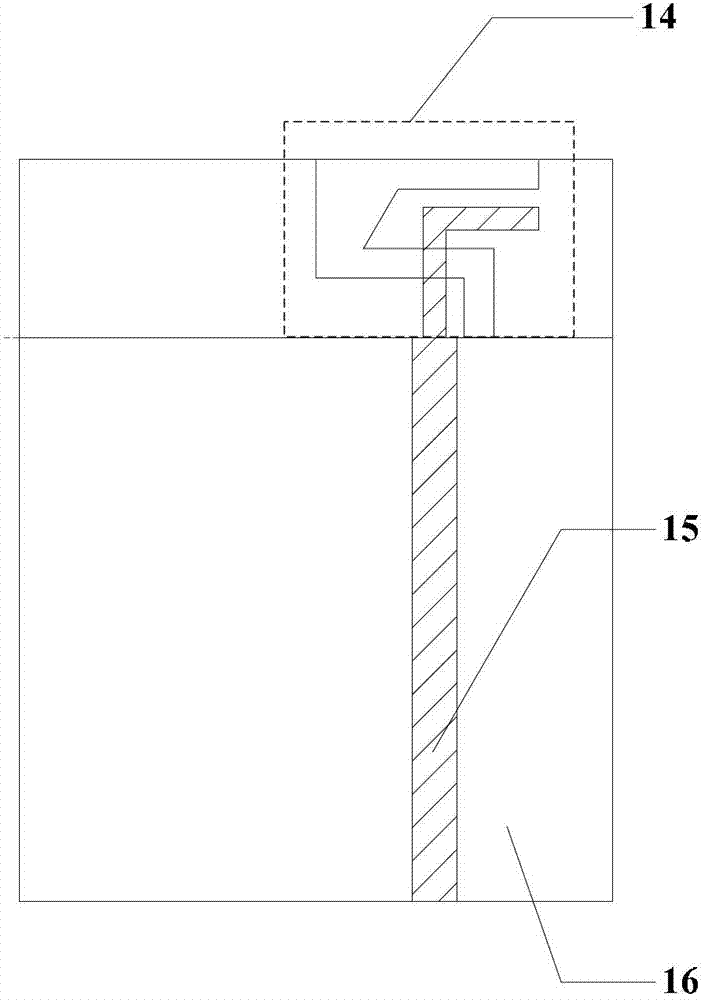
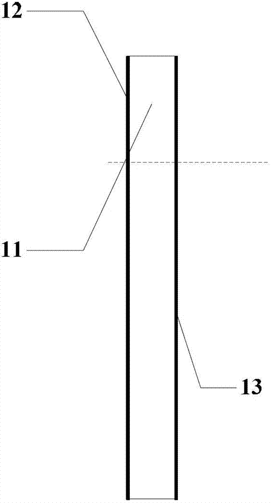
[0036] see figure 1 and figure 2 , a broadband planar printed antenna, comprising a dielectric substrate 11, wherein the front 12 of the dielectric substrate 11 is printed with a C-shaped radiating element 25 and a floor 16, and the back 13 of the dielectric substrate 11 is printed with an inverted L-shaped radiating element 30 and micro With feeder 15. The C-shaped radiation unit 25 and the inverted L-shaped radiation unit 30 constitute the antenna unit 14 . The material of the dielectric substrate used in the present invention is epoxy glass fiber (FR4), the dielectric constant is 4.4, the loss tangent is 0.02, the thickness of the dielectric substrate is H=1.6mm, the width is S2=40mm, and the length S1=50mm.

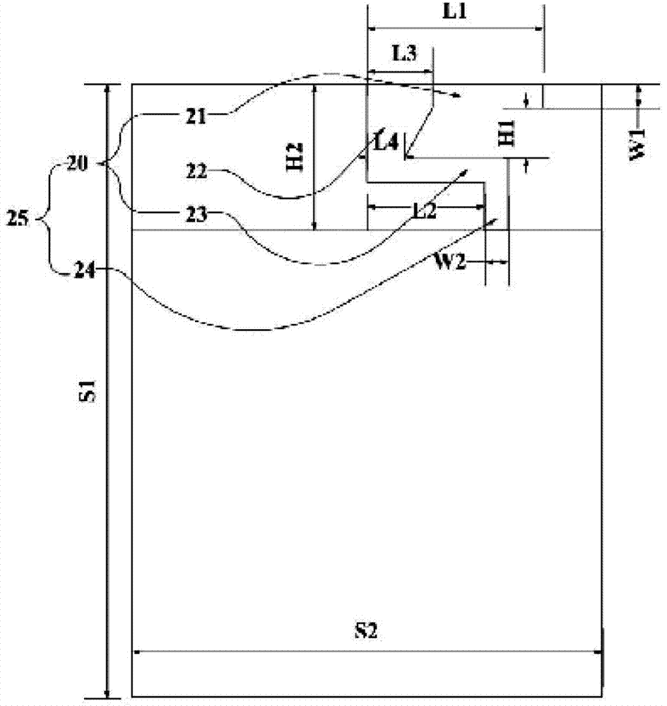
[0037] see image 3, the above-mentioned C-shaped radiation unit 25 is mainly composed of an open-end unit 20 and a short-circuit unit 24; wherein the open-end unit 20 includes a first branch 21, a second branch 23 and a gradual change branch 22, and the two ends ...


PUM


Abstract

The invention discloses a broadband planar printed antenna, which comprises a dielectric substrate, wherein the front of the dielectric substrate is printed with a similar C-shaped radiating element and a floor, and the back of the dielectric substrate is printed with a reverse L-shaped radiating element and a micro-strip feed line. A vertical branch in the reverse L-shaped radiating element and a second branch of a tail end open circuit element in the similar C-shaped radiating element are partially overlapped on a mirror image projection plane vertical to the dielectric substrate, and the reverse L-shaped radiating element and the similar C-shaped radiating element form cross coupling. The broadband planar printed antenna has the advantages of simple and compact structure and easiness in processing, has a certain gain and better omnidirectional radiation characteristics, and is especially suitable for a wireless communication device of a hand-held terminal.

Description

technical field [0001] The invention relates to a planar printed antenna, in particular to a broadband planar printed antenna. Background technique [0002] With the rapid development of wireless communication technology, while people enjoy the convenience of communication services in various frequency bands, they also put forward higher requirements for antenna designers. As the key part of transmitting and receiving wireless signals, the antenna has been paid more and more attention, and its performance index directly affects the quality of wireless communication. Especially for handheld terminal antennas, it has become one of the trends in antenna design to design a built-in antenna with compact structure, light weight, simple implementation, multi-frequency, and wide-band characteristics. Planar printed antennas have the advantages of flexible design, low profile, light weight, easy conformability, and low cost, and have attracted much attention from antenna researchers...

Claims


Application Information

Patent Timeline
IPC IPC(8): H01Q1/38H01Q1/50
Inventor 肖海林胡振
Owner ZHEJIANG UNIVIEW TECH CO LTD
Why Eureka
Try Eureka