Electrical switchgear enabling dual push rods to be driven in a pneumatic manner

A technology of electric switch and pneumatic drive, which is applied in the field of electric switchgear, can solve the problems such as difficult to guarantee airtight performance, and achieve the effect of stable operation and simple structure

Inactive Publication Date: 2015-10-28
方新刚
View PDF9 Cites 4 Cited by
  • Summary
  • Abstract
  • Description
  • Claims
  • Application Information

AI Technical Summary

Problems solved by technology

However, under frequent switching, it is difficult to guarantee this kind of airtight performance, and it is even more difficult to realize it under operation control

Method used


Image

  • Electrical switchgear enabling dual push rods to be driven in a pneumatic manner
  • Electrical switchgear enabling dual push rods to be driven in a pneumatic manner
  • Electrical switchgear enabling dual push rods to be driven in a pneumatic manner

Examples


Embodiment Construction

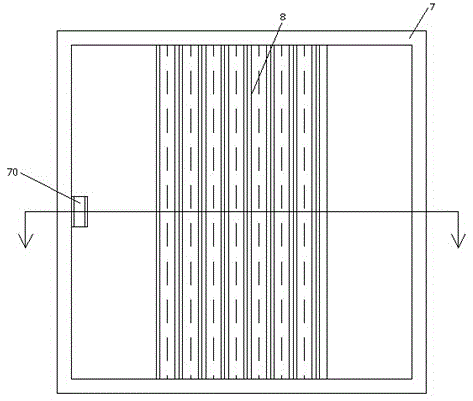
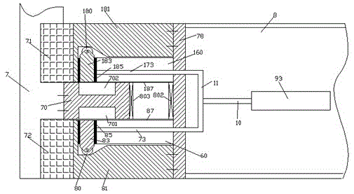
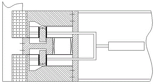
[0010] Combine below figure 1 -4 The present invention will be described in detail.

[0011] According to an embodiment, an electrical switchgear using pneumatically driven double push rods includes a cabinet body 7 and a sliding door 8 located at the front opening of the cabinet body 7, and the middle part of the frame of the cabinet body 7 is fixedly arranged toward the opening. There is a locking projection 70, and a dragging mechanism is provided at a side position of the sliding door 8 corresponding to the locking projection 70, and the dragging mechanism includes a mounting block 78 fixedly installed on the body of the sliding door 8 And the guide rail blocks 81,181 fixedly connected with the installation block 78, the opposite sides of the guide rail blocks 81,181 are provided with vertical blocking sections 810,1810 including front and rear directions from left to right, concave horizontal sections 811, 1811, the transition slope section 812, 1812 and the profile p...


PUM


Abstract

Provided is an electrical switchgear enabling dual push rods to be driven in a pneumatic manner. The electrical switchgear includes a cabinet body (7) and a sliding door (8) positioned in an opening at the front end of the cabinet body (7). A locking protrusion (70) facing the opening is fixedly disposed in the middle of a frame of the cabinet body (7). One side of the sliding door (8), corresponding to the locking protrusion (70), is provided with a drag mechanism. The drag mechanism comprises a mounting block (78) fixedly arranged on a body of the sliding door (8), and guide rail blocks (81, 181) fixedly connected to the mounting block (78). The opposite surfaces of the guide rail blocks (81, 181) are both provided with profile portions that sequentially include vertical block segments (810, 1810), inward recessed horizontal segments (811, 1811), transition inclined plane segments (812, 1812) and outward protruding horizontal segments (813, 1813).

Description

technical field [0001] The application relates to the field of electrical cabinets, in particular to an electrical switch cabinet using pneumatically driven double push rods. Background technique [0002] The operation door of the electrical switchgear needs to be opened and closed frequently to operate or maintain the electrical switches therein. Moreover, in some occasions, the electrical switchgear needs to have watertight airtight performance to ensure the normal and reliable operation of the internal electrical switching elements. However, under frequent switching, it is difficult to guarantee this airtight performance, and it is even more difficult to realize it under operation control. Contents of the invention [0003] The object of the present invention is to provide an electrical switchgear using pneumatically driven double push rods, which can overcome the above-mentioned drawbacks of the prior art. [0004] According to the present invention, an electrical sw...

Claims


Application Information

Patent Timeline
Patent Type & Authority Applications(China)
IPC IPC(8): H02B1/26
Inventor 方新刚
Owner 方新刚
Why Eureka
Try Eureka