Electrical switch cabinet with inner buffer spring

A technology of buffer springs and electrical switches, applied in substation/switch layout details, electrical components, substation/distribution device shells, etc., can solve problems such as difficulty in ensuring airtight performance, achieve simplified structure, improve service life, and operate reliably Effect

Inactive Publication Date: 2015-09-02
梁文辉
View PDF5 Cites 0 Cited by
  • Summary
  • Abstract
  • Description
  • Claims
  • Application Information

AI Technical Summary

Problems solved by technology

However, under frequent switching, it is difficult to guarantee this kind of airtight performance, and it is even more difficult to realize it under operation control

Method used


Image

  • Electrical switch cabinet with inner buffer spring
  • Electrical switch cabinet with inner buffer spring
  • Electrical switch cabinet with inner buffer spring

Examples


Embodiment Construction

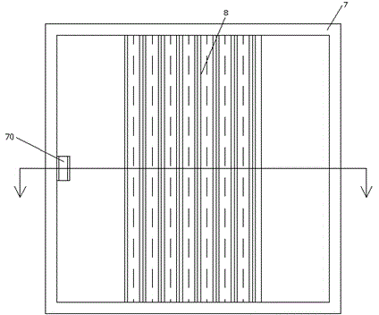
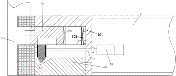
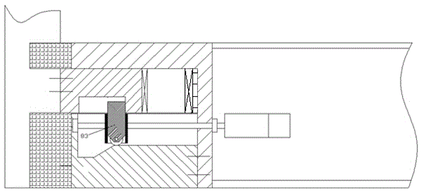
[0012] Combine below Figure 1-5 The present invention will be described in detail.

[0013] According to an embodiment, an electrical switch cabinet provided with an internal buffer spring includes a cabinet body 7 and a sliding door 8 located at the opening at the front end of the cabinet body 7. The middle part of the frame of the cabinet body 7 is fixedly arranged toward the opening. Locking projection 70, said sliding door 8 is provided with a dragging mechanism at one side corresponding to said locking projection 70, and said dragging mechanism includes a mounting block 82 fixedly installed on said sliding door 8 body and The guide rail block 81 fixedly connected with the installation block 82, the guide rail block 81 forms a cavity together with the installation block 82, and the guide rail block 81 is provided with It includes the vertical blocking section 810 in the front-rear direction, the concave horizontal section 811, the transition slope section 812 and the pro...


PUM


Abstract

Provided is an electrical switch cabinet with inner buffer springs. The switch cabinet comprises a cabinet body (7) and a sliding door (8) on the opening of the front end of the cabinet body (7). The middle position of the frame of the cabinet body (7) is fixedly provided with a locking bump (70) facing the opening. The side of the sliding door (8), corresponding to the locking bump (70), is provided with a dragging mechanism. The dragging mechanism comprises an installation block (82) fixedly installed on the body of the sliding door (8), and a guide rail block (81) fixedly connected with the installation block (82). The guide rail block (81) and the installation block (82) form a cavity. The side surface of the guide rail block (81), facing the cavity, is provided with contour portions of a vertical stopping segment (810) in front-back direction, a inner sunken horizontal segment (811), a transition slope segment (812), and an outer convex horizontal segment (813) from left to right in sequence.

Description

technical field [0001] The application relates to the field of electrical cabinets, in particular to an electrical switch cabinet provided with an internal buffer spring. Background technique [0002] Electrical Switchgear The operating door of the electrical switchgear needs to be opened and closed frequently to operate or maintain the electrical switches therein. Moreover, in some occasions, the electrical switchgear needs to have a watertight airtight performance to ensure the normal and reliable operation of the internal electrical switching elements. However, under frequent switching, it is difficult to guarantee this airtight performance, and it is even more difficult to realize it under operation control. Contents of the invention [0003] The object of the present invention is to provide an electrical switchgear provided with an inner buffer spring, which can overcome the above-mentioned drawbacks of the prior art. [0004] According to the present invention, an ...

Claims


Application Information

Patent Timeline
Patent Type & Authority Applications(China)
IPC IPC(8): H02B1/26
CPCH02B1/306
Inventor 梁文辉
Owner 梁文辉
Why Eureka
Try Eureka