
A chamfering device for a metal roller

A technology of chamfering device and metal roller, which is applied in the field of chamfering device, can solve the problems of low efficiency, poor chamfering effect, poor thermal conductivity of the roller body, etc., and achieve the effect of high efficiency and fast chamfering speed

Active Publication Date: 2017-06-23
佛山市埃申特科技有限公司
View PDF5 Cites 0 Cited by
  • Summary
  • Abstract
  • Description
  • Claims
  • Application Information

AI Technical Summary

Problems solved by technology

[0003] However, if resin materials such as polystyrene and polyimide are used as the roller body, the thermal conductivity of the roller body is poor, and nickel electroformed products are used as the roller body, although its thermal conductivity is excellent, but at temperatures above 180 ° C High temperature will cause thermal embrittlement, so in the printing equipment industry, roller bodies made of the above two materials are gradually withdrawn from the market, replaced by metal printing rollers made of thin-walled metal cylinders
[0004] For metal printing rollers made of thin-walled metal cylinders, the traditional processing equipment is to use a spinning machine. During the spinning process, the metal cladding materials of aluminum, stainless steel, nickel, titanium, copper or stainless steel and copper etc. as materials, using the spinning parts to rotate around the mandrel while moving the axis to achieve plastic processing, using this thin-walled metal cylinder can be made to play the metal's excellent heat conductivity, heat resistance, fatigue strength, Rigid roller, the end of the resulting metal printing cylinder needs to be chamfered, but the chamfering device now has poor chamfering effect and low efficiency

Method used


Image

  • A chamfering device for a metal roller
  • A chamfering device for a metal roller
  • A chamfering device for a metal roller

Examples


Embodiment Construction

[0031] The preferred embodiments of the present invention will be described below in conjunction with the accompanying drawings. It should be understood that the preferred embodiments described here are only used to illustrate and explain the present invention, and are not intended to limit the present invention.

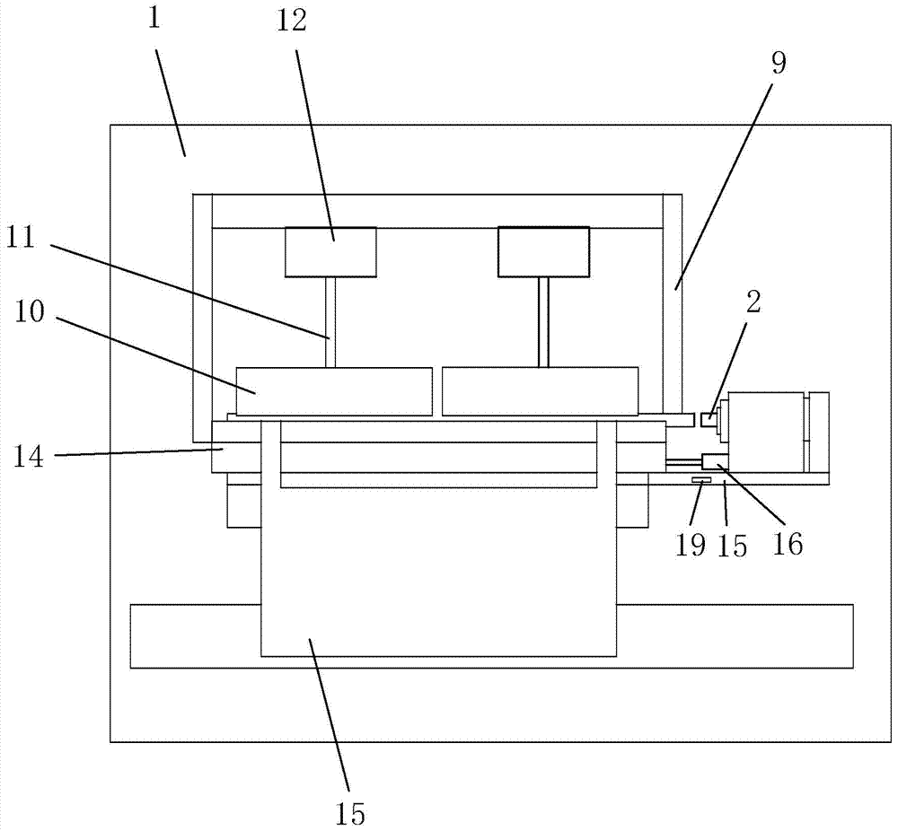
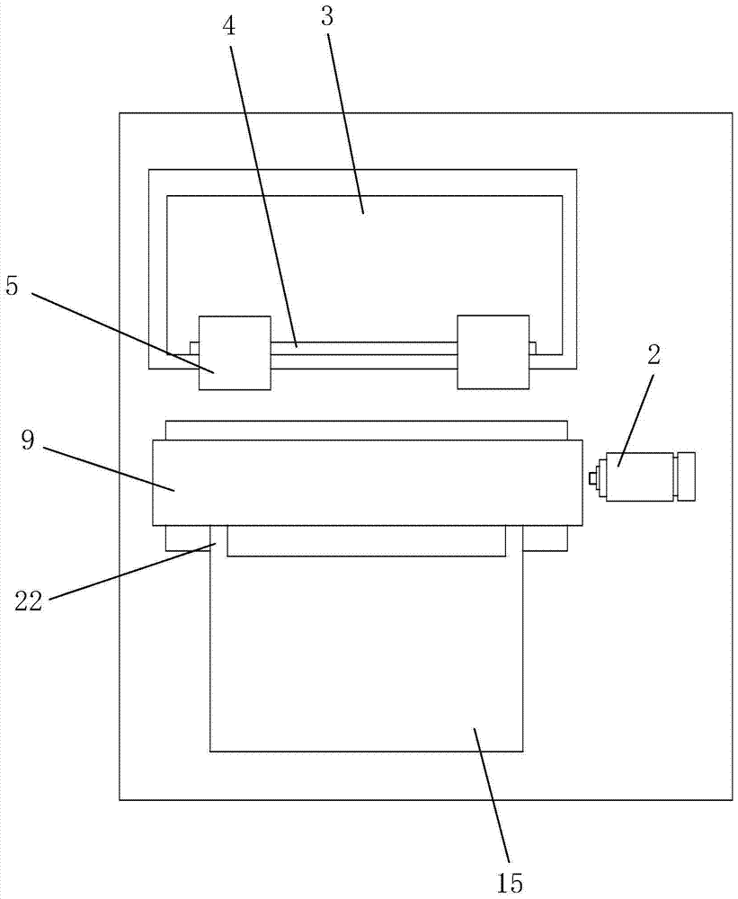
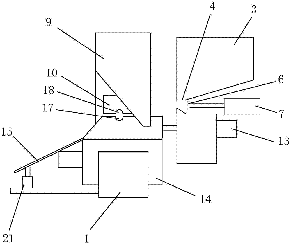
[0032] Such as Figures 1 to 3 Shown, the chamfering equipment of a kind of metal printing cylinder of the present invention comprises frame 1, and frame 1 is provided with feeding device, pushing device, roller fixing device, chamfering device and discharging device, and chamfering The angular device comprises a rotary cutting head 2 .

[0033] Wherein, the feeding device includes a storage box 3, the storage box 3 is provided with a blanking horizontal hole 4, and the side wall of the storage box 3 near the blanking horizontal hole 4 is provided with two vertical through grooves, and the storage box 3 A discharge cylinder 5 is installed, and several metal printin...


PUM


Abstract

The invention discloses a chamfering device for a metal roller. The chamfering device comprises a frame, wherein the frame is provided with a feeding device, a pushing device, a roller fixing device, a chamfering device and a discharging device; the chamfering device comprises a rotary cutting head; the feeding device comprises an accommodating box which is provided with a material discharging cross hole; the pushing device comprises a push rod and a first air cylinder; the frame is provided with the push rod corresponding to the material discharging cross hole; the push rod is fixedly connected with the first air cylinder; the accommodating box is provided with a discharging air cylinder; a piston of the discharging air cylinder is provided with a baffle corresponding to the material discharging cross hole. The overall chamfering equipment for a metal printed roller is capable of realizing feeding, chamfering and discharging operations, rapid in chamfering speed and high in efficiency.

Description

technical field [0001] The invention relates to a chamfering device, in particular to a chamfering device of a metal roller. Background technique [0002] Usually used as rolls for optical film manufacturing, nanoimprinting, large and small electronic imaging printers, and high-precision printing, polystyrene films and polyimide films with a wall thickness in the range of 0.03 to 0.3 mm are often used. In addition, some are electroplated in nickel plating, and are produced by nickel electroforming in which an electroformed product in which nickel metal is deposited on a cylindrical matrix is ​​extracted from the matrix. The rolls for the above-mentioned purposes need to be used in the process of continuous heating, pressurization, cooling, peeling, etc., so it is desirable to have good thermal conductivity and heat resistance. In addition, because the rolls for the above-mentioned purposes are used as rotating bodies, Therefore, excellent fatigue strength and rigidity are a...

Claims


Application Information

Patent Timeline
Patent Type & Authority Patents(China)
IPC IPC(8): B23D79/04
CPCB23D79/04
Inventor 刘江
Owner 佛山市埃申特科技有限公司
Learn More