
a frame structure

A technology for frames and temples, which is applied in the directions of glasses/goggles, optics, instruments, etc., to achieve the effect of simple structure and reduced pressure holding force.

Active Publication Date: 2018-05-08
CHENGDU ZHIRONG ZHICHUANG INTPROP MANAGEMENT CO LTD
View PDF4 Cites 0 Cited by
  • Summary
  • Abstract
  • Description
  • Claims
  • Application Information

AI Technical Summary

Problems solved by technology

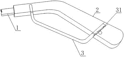
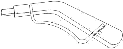
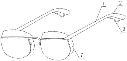
[0005] In order to solve the above problems, the present invention provides a spectacle frame structure through the following technical points to solve the problem: a spectacle frame structure, including a temple body, a spectacle frame and ear hooks fixed on the free ends of the temple body, and also includes a A curved rod-shaped adjustment rod made of metal, any one end of the adjustment rod is connected with the free end of the earhook, the other end of the adjustment rod is connected with the connecting end of the earhook or the temple body, and the adjustment rod is connected with the earhook or The connection points of the mirror leg body are all located on the bottom surface of the earhook or the mirror leg body when the mirror leg structure is worn; There are multiple tooth slots distributed in the direction, and the temple body or the ear hook is provided with a socket corresponding to the end of the adjustment rod with the tooth slot, and the end of the adjustment rod with the tooth slot is located in the socket. A deformation adjustment part is also provided, and the deformation adjustment part includes a bolt connected to the ear hanger or the body of the mirror leg, a gear fixed on the bolt, the teeth of the gear mesh with the tooth grooves, and the mirror frame is also fixed Eye protection frame with detachable connection with the frame

Method used


Image

  • a frame structure
  • a frame structure
  • a frame structure

Examples


Embodiment 1

[0026] Such as Figure 1 to Figure 4 As shown, a mirror frame structure includes a mirror leg body 1, a mirror frame and an ear hook 2 fixed on the free end of the mirror leg body 1, and also includes a curved rod-shaped adjusting rod 3 made of metal, the adjusting rod Any one end of 3 is connected with the free end of the earhook 2, the other end of the adjustment rod 3 is connected with the connection end of the earhook 2 or the temple body 1, and the connection points of the adjustment rod 3 and the earhook 2 or the temple body 1 are uniform. It is located on the bottom surface of the earhook 2 or the temple body 1 when the temple structure is worn; at least one end of the adjustment rod 3 is also provided with a device located on the same side of the adjustment rod 3 and distributed along the length direction of the adjustment rod 3 . A plurality of tooth grooves 31, the temple body 1 or the ear hook 2 is provided with a socket corresponding to the end of the adjustment ro...

Embodiment 2

[0031] The present embodiment is further limited on the basis of embodiment 1, as Figure 1 to Figure 4 As shown, as a realization scheme of the adjustment rod 3 with a simple structure and easy realization, the adjustment rod 3 is formed by bending a round steel wire or a steel bar made of stainless steel.

[0032] As a structural form of the adjustment rod 3 that is light in weight, easy to be deformed by force, and has sufficient supporting capacity for glasses, the diameter of the round steel wire is between 1mm and 2mm.

[0033] As a structural form of the adjusting rod 3 that is beneficial to increase the contact area between the mirror leg body 1 and the human body and is beneficial to the user's wearing comfort, the longitudinal section of the steel bar is rectangular in shape with rounded chamfered edges, and the mirror When the leg structure is in the worn state, the projection width of the adjusting rod 3 on the horizontal plane is equal to the width of the bottom s...

Embodiment 3

[0037] This embodiment is further limited on the basis of any scheme provided by the above embodiments, such as Figure 1 to Figure 4 As shown, as a structural form of the adjusting rod 3 that facilitates the elastic deformation or plastic deformation in the central part of the adjusting rod 3 and the shape retention of the adjusting rod 3 after deformation, the longitudinal cross-sectional area of ​​the parts located at both ends of the adjusting rod 3 Greater than the longitudinal cross-sectional area of ​​the part located in the center of the adjustment rod 3 .


PUM


Abstract

The invention discloses a spectacle frame structure, which includes a mirror leg body and ear hangers, and also includes a curved rod-shaped adjusting rod made of metal material, any end of the adjusting rod is connected with the free end of the ear hanger, The other end is connected with the connecting end of the ear hook or the body of the mirror leg; at least one end of the adjustment rod is also provided with a plurality of tooth grooves located on the same side of the adjustment rod and distributed along the length direction of the adjustment rod, and the body of the mirror leg or the ear A socket corresponding to the end of the adjustment rod with a tooth groove is arranged on the hanger, and a deformation adjustment part is also arranged on the temple of the glasses, and the deformation adjustment part includes bolts and gears connected to the ear hook or the body of the mirror leg. The invention has simple structure, high precision of adjustable deformation of the adjusting rod, the user can conveniently adjust the shape of the adjusting rod to obtain good wearing comfort, and at the same time, can adjust the clamping force of the glasses according to specific conditions, which is beneficial to the further popularization of online glasses .

Description

technical field [0001] The invention relates to the field of book reading aid devices, in particular to a mirror frame structure. Background technique [0002] The eye is an important visual organ of the human body. Due to people's frequent incorrect reading and viewing habits, excessive eye use, and increasing age, myopia is becoming more and more common, which makes the wearing rate of glasses in the crowd higher and higher. [0003] Existing frame glasses are made up of lens and mirror frame, and mirror frame comprises the mirror leg that is made up of mirror leg body and ear hook again. The glasses fix the lenses in front of the eyes through the bridge of the nose, cheeks and ears of the human body to achieve correct wearing. However, most of the temples of the existing frame glasses are integral structures, that is, the body of the temples is fixedly connected with the ear hooks. During the wearing process of myopia patients, it is often encountered that different face...

Claims


Application Information

Patent Timeline
Patent Type & Authority Patents(China)
IPC IPC(8): G02C5/20
Inventor 邓利平
Owner CHENGDU ZHIRONG ZHICHUANG INTPROP MANAGEMENT CO LTD
Learn More