Vacuum cleaner nozzle comprising a light source

A vacuum cleaner and light source technology, applied in the installation of suction nozzles and electrical equipment, etc., can solve the problems of cost increase, broken, and cost increase

Active Publication Date: 2015-11-18
SEB SA
View PDF6 Cites 5 Cited by
  • Summary
  • Abstract
  • Description
  • Claims
  • Application Information

AI Technical Summary

Problems solved by technology

The first disadvantage is that multiple light sources should be set up in order to properly illuminate the clean ground
The costs associated with this lighting option also increase the
A second disadvantage is that these sources are exposed to impacts and therefore risk shattering, which requires the use of transparent walls to protect the sources, which also adds to the cost

Method used


Image

  • Vacuum cleaner nozzle comprising a light source
  • Vacuum cleaner nozzle comprising a light source
  • Vacuum cleaner nozzle comprising a light source

Examples


Embodiment Construction

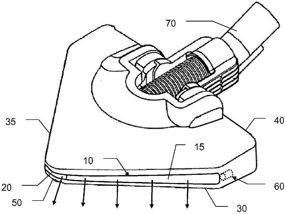
[0035] figure 1 A vacuum cleaner head is shown having a triangular shape. The vacuum cleaner head includes a left front edge 30 and a right front edge 35 which join forwardly to form a tip 50 . At the rear, the leading edges 30 and 35 are connected by a rear face 40 . In addition, the vacuum cleaner head comprises a connection 70 for allowing connection with the duct of the vacuum cleaner.

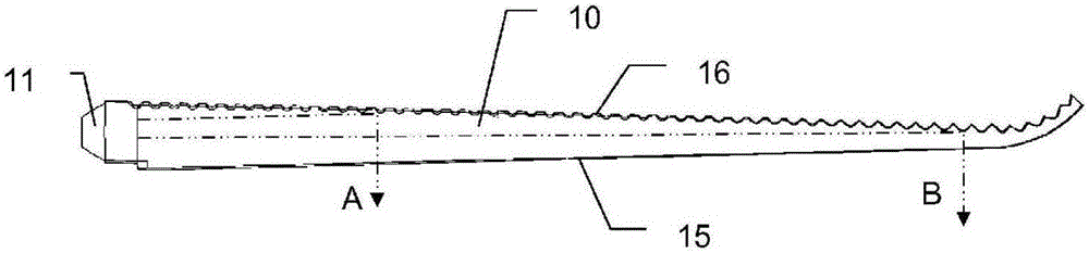
[0036] The vacuum cleaner head comprises a light guide 10 whose outer face forms a projection surface 15 . The projection surface 15 is arranged for projecting a beam of light on the floor to be cleaned as indicated by the arrows shown. The light beam projected by the projection surface 15 is formed by the light source 60, which is shown by dashed lines since it is arranged inside the housing of the main body of the vacuum cleaner head. The light guide 10 collects at one of its ends the light emitted by the light source 60 and transmits this emitted light over its entire length towards...


PUM


Abstract

The invention relates to a vacuum cleaner nozzle including: a nozzle body having at least one leading edge (30, 35), at least one light source (60) arranged to emit light, at least one projection surface (15) arranged on said at least one leading edge (30, 35), for receiving the light emitted by said at least one light source (60) and for projecting a light beam for lighting a floor to be cleaned, characterized in that said at least one projection surface (15) is arranged along said at least one leading edge (30, 35) and in that the vacuum cleaner nozzle includes transmission means arranged between said at least one light source (60) and said at least one projection surface (15), for transmitting and distributing the light emitted by said at least one light source (60) along said at least one projection surface (15).

Description

technical field [0001] The present invention generally relates to a vacuum cleaner nozzle for equipping a vacuum cleaner. Background technique [0002] Vacuum cleaner heads are known in the prior art, the front edge of which is equipped with a light source in order to illuminate the floor to be cleaned located in front of the front edge. This type of vacuum cleaner head has two disadvantages. The first disadvantage is that multiple light sources should be provided in order to properly illuminate the clean floor being treated. The costs associated with this lighting option also increase. A second disadvantage is that these sources are exposed to impacts and therefore risk shattering, which requires the use of transparent walls to protect the sources, which also adds to the cost. Contents of the invention [0003] The object of the present invention is to overcome the disadvantages of the above-mentioned documents of the prior art and in particular first to provide a vacu...

Claims


Application Information

Patent Timeline
Patent Type & Authority Applications(China)
IPC IPC(8): A47L9/02A47L9/30
CPCA47L9/02A47L9/30
Inventor 史蒂法纳·勒阿帕雷蒂安
Owner SEB SA
Why Eureka
Try Eureka