Side arm release system for eyeglass frame with changeable temple pieces

A technology of eyeglass frame and side arm, applied in the field of eyeglass system

Inactive Publication Date: 2014-03-12
SILVER GLOBAL MFG
View PDF7 Cites 2 Cited by
  • Summary
  • Abstract
  • Description
  • Claims
  • Application Information

AI Technical Summary

Problems solved by technology

However, none of the above techniques teaches the long-needed simple, cost-effective and durable solution in the prior art for eyeglass frame sidearm release systems that can be brought to market at a reasonable price point

Method used


Image

  • Side arm release system for eyeglass frame with changeable temple pieces
  • Side arm release system for eyeglass frame with changeable temple pieces
  • Side arm release system for eyeglass frame with changeable temple pieces

Examples


Embodiment Construction

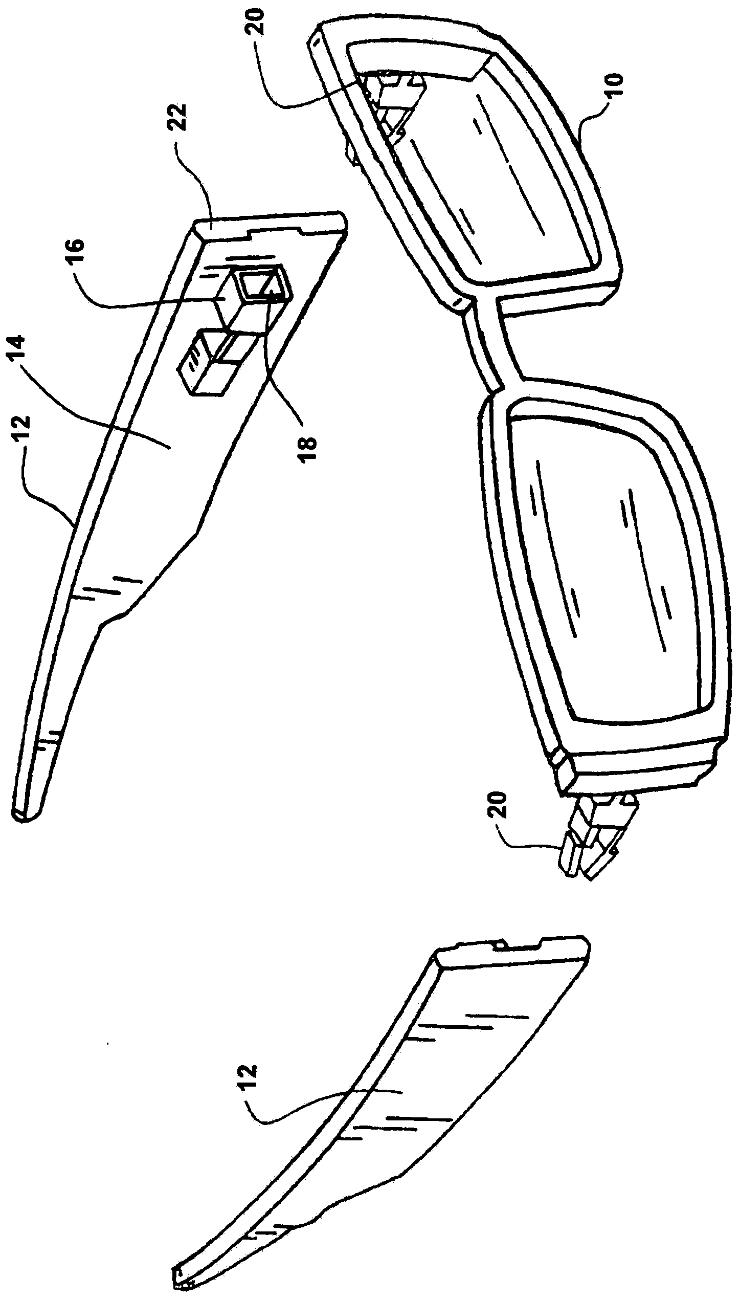
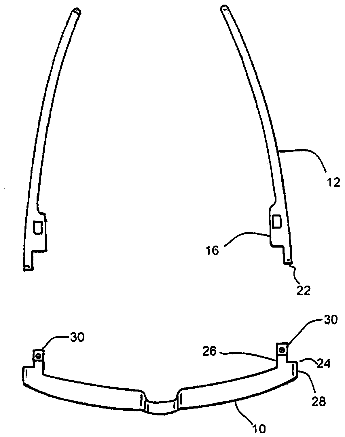
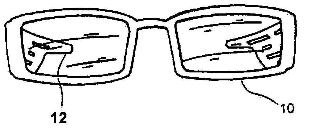
[0018] Reference figure 1 Is an exploded perspective view showing a spectacle frame 10 including side arms 12. As can be noted, each side arm is also referred to herein as a temple member. The temple member has an inner surface 14 on which a female bayonet clip 16 is provided. The inner surface 14 of the leg member 12 is integrally formed. Each female bayonet clip is characterized by a mouth or opening 18 that is suitable for snap-fit ​​engagement in Figure 5 The opposite male bayonet clip 20 is shown in more detail in the view. Each temple member 12 includes a forward outermost surface 22, which is referred to more fully below and described in figure 2 Shown in more detail in the top view. More specifically, the outermost surface 22, hereinafter also referred to as the cam surface 22, is adapted to be complementarily placed between the fulcrum 24 and the journal 26 (see figure 2 with Figure 5 ), the fulcrum 24 and the journal 26 protrude backward in a direction away from ...


PUM


Abstract

A side arm release system for an eyeglass frame includes front frame having outer edges, each of the edges terminating in a vertical line substantially parallel to a plane defined by the eyeglasses or the like held within the front frame. The vertical line functions as a fulcrum for the release function. The system further includes a pair of axle journals, one each of the journals of the pair integrally depending from the inner surface of each outer end of the front frame, the journal projecting in a direction generally normal to the plane of the eyeglasses held within the front frame. The journals are located proximally to the fulcrum within a dimension having a width of the forward-most ends of side arms. The system also includes a pair of male bayonet clips, each rotationally dependent at one end from axles within respective the journals of the eyeglass frame, and inwardly of the fulcrum in the direction of a nose bridge of the front frame. Each of the temple pieces exhibit a forward end terminating in a vertical camming surface which contacts the fulcrum upon rotation of the arms or temple members. A pair of female bayonet clips are proportioned for complemental engagement of opposing male bayonet clips, the female clips formed integrally upon inner sides of each temple piece proximally to each of the male bayonet clips when the male clips are press- fitted into the female clips. The outward rotation of temple members causes a lever action of the camming surface upon the fulcrum, pulling on the male bayonet clip. Rotation of the eyeglass frame oppositely in direction to the rotation of the side arm will also pull the male bayonet clip out of engagement with its associated female clip and in the direction of the eyeglass frame.

Description

Technical field [0001] The invention relates to a spectacle system with temples or temple pieces that can be changed in a selectable manner. Background technique [0002] In the past, glasses having temple pieces have been proposed, the configuration, color, or design of the temple pieces can be changed. For example, U.S. Patent No. 5,321,442 (1994) entitled Spectacles with, for example, removable lenses, side bars, and adjustable temples by Albanese discloses spectacles with removable temples including the following sleeves, The sleeve can be stuck on the temple piece or slipped from the temple piece. In Gitlin's U.S. Patent No. 3,582,192 (1971) named Detachable Decorative Sleeves for Glasses, Cooper's U.S. Patent No. 5,185,620 (1993) named Glasses System, and Kirschner's U.S. Patent No. 5,185,620 (1993) named Decorative Sunglasses US Patent No. 5,652,635 (1997) teaches other concepts for providing eyeglasses or sunglass frame systems with temple pieces that can be changed in ...

Claims


Application Information

Patent Timeline
Patent Type & Authority Applications(China)
IPC IPC(8): G02C5/14G02C5/20G02C11/02G02C13/00
CPCG02C5/146
Inventor M·A·西尔弗
Owner SILVER GLOBAL MFG
Why Eureka
Try Eureka