A circulating fluidized bed reactor device

A circulating fluidized bed and reactor technology, which is applied in the field of circulating fluidized bed reactor devices, can solve the problems of uncompact reactors, and achieve the effects of low cost, easy manufacture, and cost reduction

Inactive Publication Date: 2004-03-17
GENERAL ELECTRIC TECH GMBH
View PDF1 Cites 2 Cited by
  • Summary
  • Abstract
  • Description
  • Claims
  • Application Information

AI Technical Summary

Problems solved by technology

[0005] Therefore, although the reaction chamber and the back channel are compact, the reactor is not compact due to the arrangement of these separators

Method used


Image

  • A circulating fluidized bed reactor device
  • A circulating fluidized bed reactor device
  • A circulating fluidized bed reactor device

Examples


Embodiment Construction

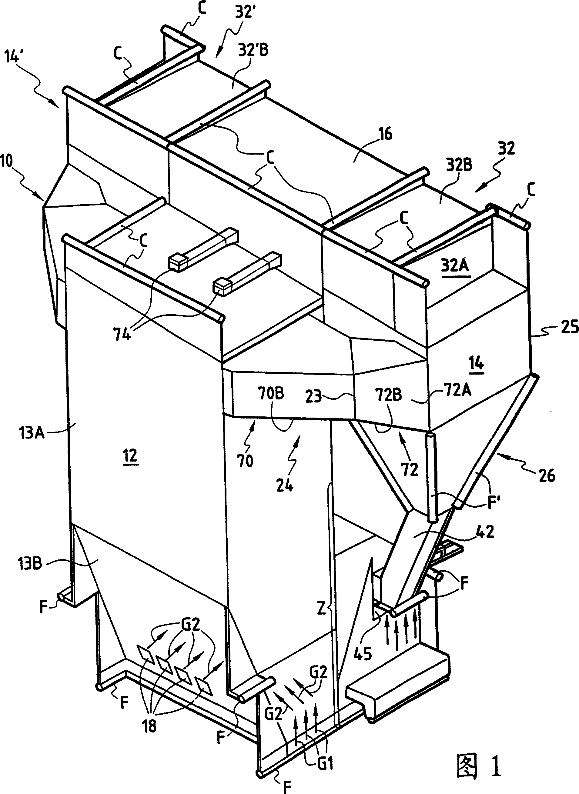
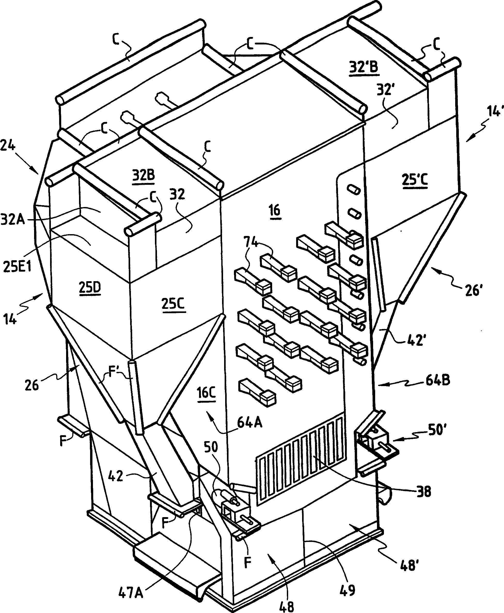
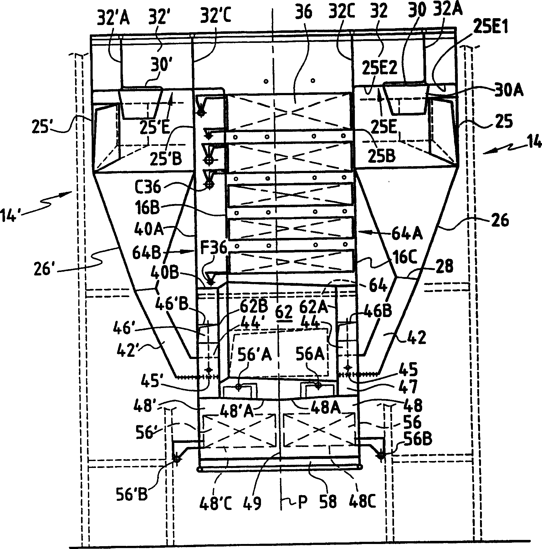
[0059] 1 to 6 show a fluidized bed reactor unit 10 having an upright combustion reaction chamber 12 , a centrifugal separator 14 and a rear channel 16 .

[0060] In the horizontal direction, reaction chamber 12 is delimited by walls 12A, 12B, 12C and 12D. As shown in FIG. 3 , the horizontal section of the reaction chamber 12 is substantially rectangular. In the example shown in the figures, the side walls 12B, 12D and the rear wall 12C are planar walls extending in the vertical direction.

[0061] The front wall 12A has an upper vertical planar portion 13A and a lower planar portion 13B which is inclined relative to the vertical so that the cross-sectional area of ​​the reaction chamber 12 increases upward. The inclination angle α between the lower planar portion 13B and the vertical is approximately 15° to 30° (see Figure 5 ).

[0062] The reaction chamber 12 has several inlets 18 located below one third of the lower planar portion 13B for the entry of solid materials suc...


PUM


Abstract

The circulating fluidized bed reactor device comprising a reactor chamber (12) delimited horizontally by walls, a centrifugal separator (14) and a back pass (16) for heat recovery, the reactor device comprising means for introducing a fluidizing gas into the reactor chamber and for maintaining a fluidized bed of particles in said chamber, means (24) for transferring gas to be dedusted from the reactor chamber into the separator, means (42) for discharging separated particles from the separator and means for transferring dedusted gas from the separator into the back pass. The reactor chamber and the separator both have a common wall with the back pass.

Description

technical field [0001] The present invention relates to a circulating fluidized bed reactor unit comprising: a reaction chamber defined horizontally by walls; a centrifugal separator; a rear channel for recovering heat; for introducing fluidization gas into Reaction chamber and means for holding the particles of the fluidized bed in said reaction chamber; means for conveying the gas to be dedusted from the reaction chamber into the separator; means for discharging the particles separated from the separator Means; means for conveying dedusted gas from the separator to a rear channel having a common wall with said reaction chamber. [0002] More precisely, such a reactor device is a boiler device in which fuel particles (to which particles of adsorbent may be suitably added for the purpose of adsorption of sulfur) are combusted in a reaction chamber, which is also referred to as Known as a furnace or combustion chamber, where the heat generated is recovered in a rear channel, s...

Claims


Application Information

Patent Timeline
Patent Type & Authority Applications(China)
IPC IPC(8): F23C10/10
CPCF23C10/10
Inventor 丹尼尔·巴廖内吉恩·克劳德·赛梅代德皮埃尔·戈维尔吉恩·泽维尔·莫里以玛利·弗洛雷斯阿兰·夸兰塔克里斯蒂安·博南
Owner GENERAL ELECTRIC TECH GMBH
Why Eureka
Try Eureka