
A control system and method based on air conditioning load forecasting

A technology of air conditioning load and control system, applied in the field of control, can solve the problems of low control accuracy, high failure rate, inconsistent changes in cooling capacity and load, etc.

Active Publication Date: 2018-03-02
ELECTRIC POWER RES INST STATE GRID SHANXI ELECTRIC POWER
View PDF5 Cites 0 Cited by
  • Summary
  • Abstract
  • Description
  • Claims
  • Application Information

AI Technical Summary

Problems solved by technology

The traditional automatic control method is to control through instruments, meters and regulators. This control method is simple and easy to implement, but the disadvantage is that the control accuracy is low and the failure rate is high.
[0004] To sum up, the air-conditioning system in the prior art may cause the problem of inconsistency between the cooling capacity and the load change, so the air-conditioning system cannot operate in the state of optimal energy efficiency, and cannot guarantee the requirements of constant temperature and humidity and energy saving

Method used


Image

  • A control system and method based on air conditioning load forecasting
  • A control system and method based on air conditioning load forecasting
  • A control system and method based on air conditioning load forecasting

Examples


Embodiment Construction

[0068] In order to make the purpose, technical solutions and advantages of the embodiments of the present invention clearer, the technical solutions in the embodiments of the present invention will be clearly and completely described below in conjunction with the drawings in the embodiments of the present invention. Obviously, the described embodiments It is a part of embodiments of the present invention, but not all embodiments. Based on the embodiments of the present invention, all other embodiments obtained by persons of ordinary skill in the art without creative efforts fall within the protection scope of the present invention.

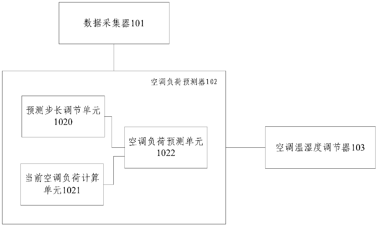
[0069] The embodiment of the present invention proposes a control system based on air conditioner load forecasting, see figure 1 , the system consists of:

[0070] The data collector 101 is used to collect indoor temperature and humidity information and outdoor temperature and humidity information at the site where the air conditioner is located ...


PUM


Abstract

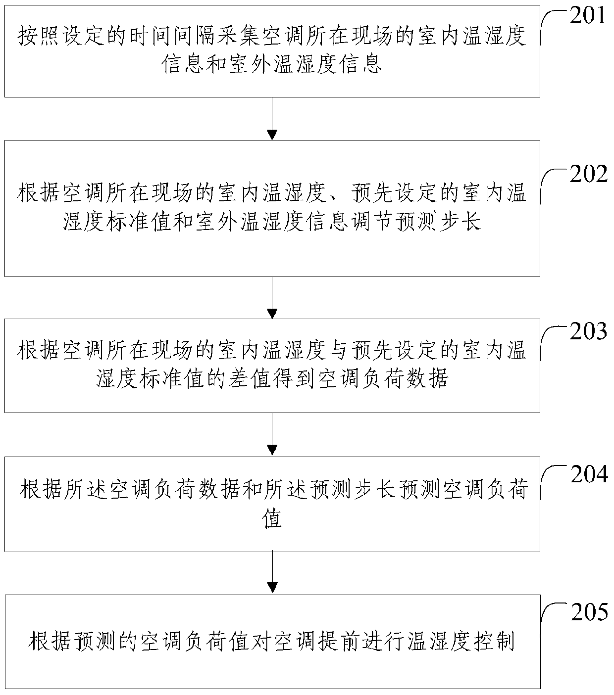
The invention provides a control system and method based on air conditioning load prediction. The control system comprises a datum collector, an air conditioning load predictor, a current air conditioning load computing unit and an air conditioning load predicting unit. The datum collector is used for collecting indoors temperature and humidity information and outdoors temperature and humidity information of the site where an air conditioner is located according to preset time intervals, and transmitting the information to the air conditioning load predictor. The air conditioning load predictor comprises a prediction step-size regulating device which is used for regulating a prediction step-size according to the indoors temperature and humidity information of the site where the air conditioner is located, preset standard values of indoor temperature and humidity and the outdoors temperature and humidity information, wherein the initial value of the prediction step-size is preset. The current air conditioning load computing unit is used for obtaining a current air conditioning load datum according to the difference value between the indoors temperature and humidity information of the site where the air conditioner is located and the preset standard values of indoor temperature and humidity. The air conditioning load predicting unit is used for predicting an air conditioning load value according to the current air conditioning load datum and the prediction step-size. The control system and method based on the air conditioning prediction are capable of controlling the temperature and humidity more accurately and achieving energy conservation to a great degree.

Description

technical field [0001] The invention relates to the technical field of control, in particular to a control system and method based on air conditioning load prediction. Background technique [0002] The energy problem has been paid more and more attention. At present, the energy consumption of buildings has accounted for more than 27% of the total energy consumption of the society. In buildings, the energy consumption of air conditioners accounts for more than 40% of the energy consumption of buildings. Energy saving of air-conditioning systems in buildings has become a hot spot in the field of energy-saving, and it is of great theoretical and practical significance to increase the research on air-conditioning energy-saving technologies. [0003] With the development of science, the requirements for constant temperature and humidity in the production process have gradually increased, such as knitwear, papermaking, medicine, food, data center computer room, etc. The central a...

Claims


Application Information

Patent Timeline
Patent Type & Authority Patents(China)
IPC IPC(8): F24F11/64F24F11/61F24F11/88F24F110/10F24F110/12F24F110/20F24F110/22
CPCF24F11/30F24F2110/00F24F2110/10F24F2110/12F24F2110/20F24F2110/22F24F2140/50
Inventor 周自强么利中谷大丰安学民张宇杨大哲孙刚
Owner ELECTRIC POWER RES INST STATE GRID SHANXI ELECTRIC POWER
Learn More