An air spring bending fatigue testing machine
An air spring and bending fatigue technology, which is applied in the field of air spring bending fatigue testing machine, can solve problems such as inspection, and achieve the effects of easy use, bending fatigue inspection, and low cost
- Summary
- Abstract
- Description
- Claims
- Application Information
AI Technical Summary
Problems solved by technology
Method used
Image

Examples
Embodiment 1
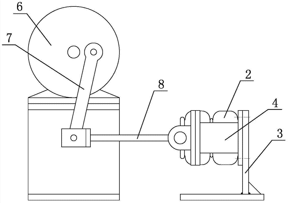
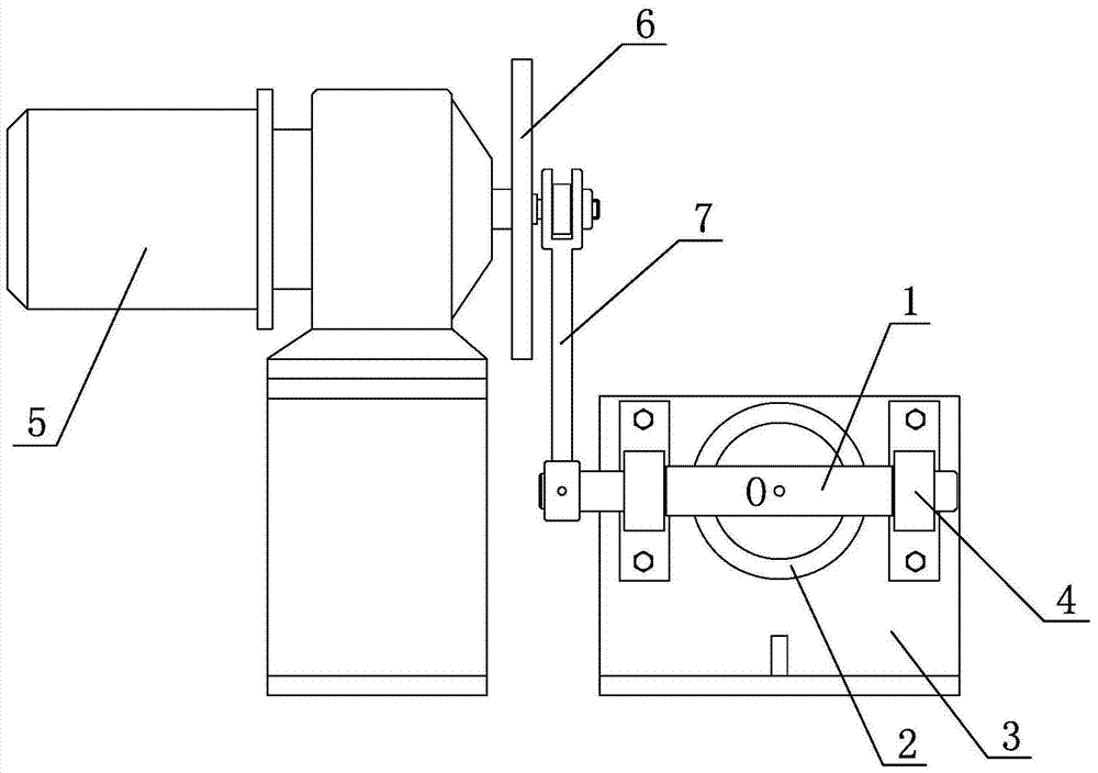
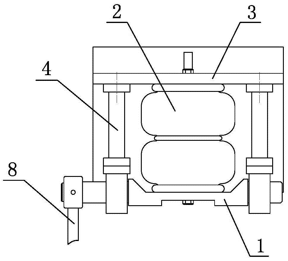
[0021] Embodiment 1: As shown in the figure, an air spring bending fatigue testing machine includes a rotating shaft 1 and a frame 3 for fixing the air spring 2, and the frame 3 is fixed with two shafts parallel to the air spring 2 Connecting rod 4, the two connecting rods 4 are respectively located on both sides of the air spring 2, the rotating shaft 1 is axially connected to the connecting rod 4, the rotating shaft 1 is fixedly connected to the center point O of the end of the air spring 2 and is connected to the axial direction of the air spring 2 Vertically, the part in contact with the air spring 2 on the rotating shaft 1 is flat, and the rotating shaft swing driving mechanism is connected to the rotating shaft 1 to drive the air spring 2 to bend. The rotating shaft swing driving mechanism includes a driving motor 5, a turntable 6, a rocker 7 and Fork 8, the turntable 6 is fixedly connected coaxially with the drive shaft of the drive motor 5, one end of the rocker 7 is ec...
Embodiment 2
[0022] Embodiment 2: As shown in the figure, an air spring bending fatigue testing machine includes a rotating shaft 1 and a frame 3 for fixing the air spring 2. Connecting rod 4, the two connecting rods 4 are respectively located on both sides of the air spring 2, the rotating shaft 1 is axially connected to the connecting rod 4, the rotating shaft 1 is fixedly connected to the center point O of the end of the air spring 2 and is connected to the axial direction of the air spring 2 Vertically, the part in contact with the air spring 2 on the rotating shaft 1 is flat, and the rotating shaft swing driving mechanism is connected to the rotating shaft 1 to drive the air spring 2 to bend. The rotating shaft swing driving mechanism includes a driving motor 5, a turntable 6, a rocker 7 and Swing bar 8, turntable 6 is coaxially fixedly connected with the drive shaft of drive motor 5, one end of rocking bar 7 is eccentrically connected with turntable 6, and a swing angle adjustment mec...
Embodiment 3
[0023] Embodiment 3: As shown in the figure, an air spring bending fatigue testing machine includes a rotating shaft 1 and a frame 3. Two connecting rods 4 parallel to the axial direction of the air spring 2 are fixedly arranged on the frame 3, and the two connecting rods are connected The rods 4 are respectively located on both sides of the air spring 2. The rotating shaft 1 is connected to the connecting rod 4. The rotating shaft 1 is fixedly connected to the center point O of the end of the air spring 2 and is perpendicular to the axial direction of the air spring 2. The rotating shaft 1 is connected to the center point O of the air spring 2. The contact part of the air spring 2 is flat, the frame 3 is screwed with an adjusting screw 9, the adjusting screw 9 is parallel to the connecting rod 4, the end of the adjusting screw 9 is integrally provided with an adjusting plate 91 for fixing the air spring 2, The adjusting screw 9 is fixed to the frame 3 through double nuts 92. T...
PUM
 Abstract
Description
Claims
Application Information
 - R&D
- Intellectual Property
- Life Sciences
- Materials
- Tech Scout
- Unparalleled Data Quality
- Higher Quality Content
- 60% Fewer Hallucinations
Browse by: Latest US Patents, China's latest patents, Technical Efficacy Thesaurus, Application Domain, Technology Topic, Popular Technical Reports.
© 2025 PatSnap. All rights reserved.Legal|Privacy policy|Modern Slavery Act Transparency Statement|Sitemap|About US| Contact US: help@patsnap.com