
flow distribution device

A technology of distributor, mass flow, applied in the direction of separation method, fluid flow, separation of dispersed particles, etc.

Inactive Publication Date: 2018-03-30
LUMMUS TECH INC
View PDF6 Cites 1 Cited by
  • Summary
  • Abstract
  • Description
  • Claims
  • Application Information

AI Technical Summary

Problems solved by technology

Such cracks disadvantageously allow leakage, which can pose a significant safety risk if the fluid be

Method used


Image

  • flow distribution device
  • flow distribution device
  • flow distribution device

Examples


Embodiment

[0087] Computational Fluid Dynamics (CFD) was used to study the flow patterns within the adsorption system produced by the upper and lower distributors of the embodiments disclosed herein. The CFD studies were performed using the following conditions: all porous media were treated as laminar flow zones; the gas mixture (hydrogen and methane) was modeled as an ideal gas; the flow in the inlet and outlet pipes was modeled as turbulent flow using the standard k-e model; the vessel was considered to be in 313K isothermal; constrained porosity, inertial and viscosity tensors are both simulated isotropically (Ergun simplified); the vessel is divided into 8 regions (refer to Figure 7 Figures 1-8 shown in , and methane is linearly removed from the porous media arranged in regions 4-6 with the aid of a negative mass source term.

[0088] The inlet composition included 85.1 wt% methane and 14.9% hydrogen with a mass flow rate of 1.199 kg / s. The density of the mixture is 6.4kg / m 3 and...


PUM


Abstract

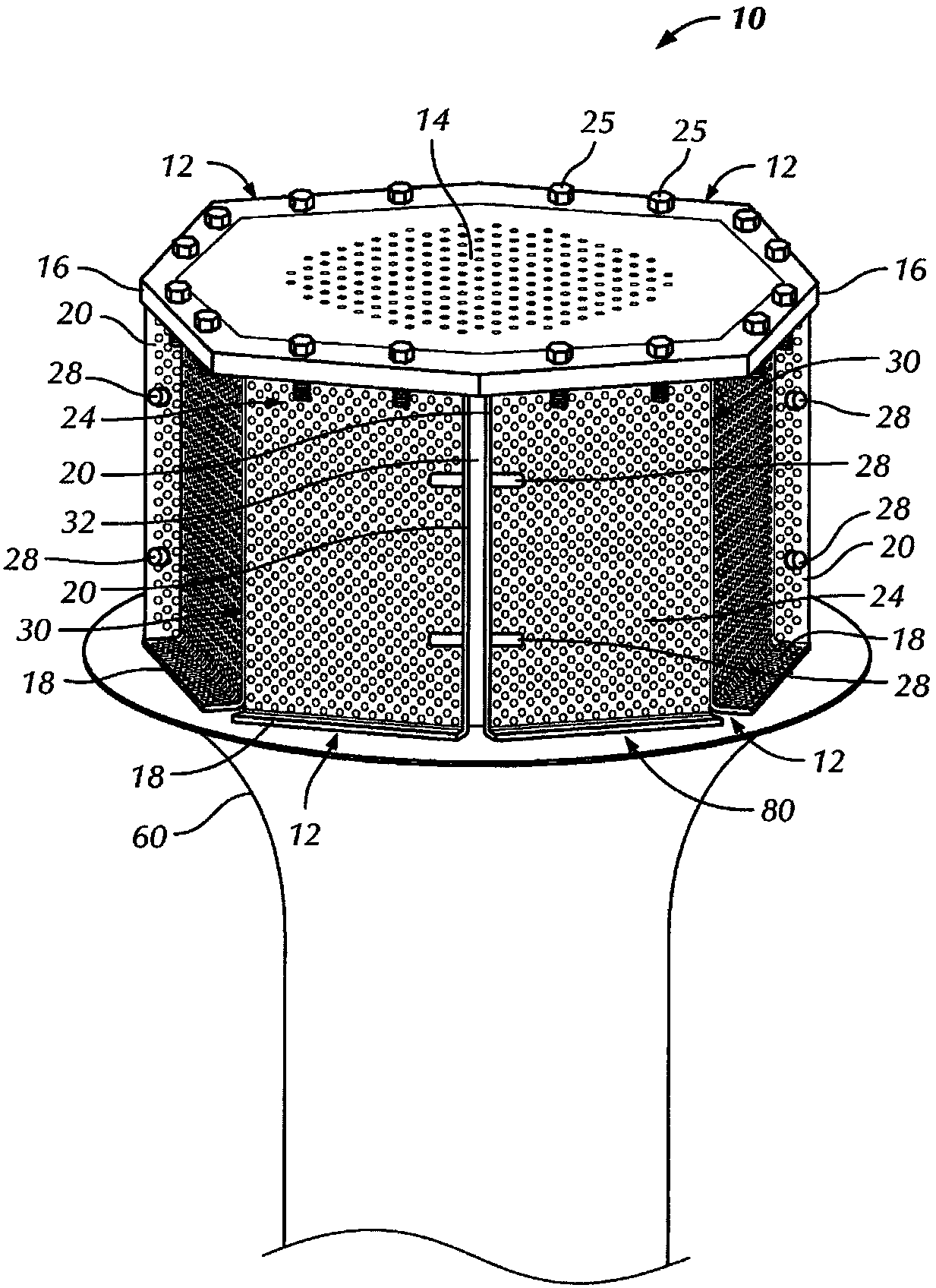
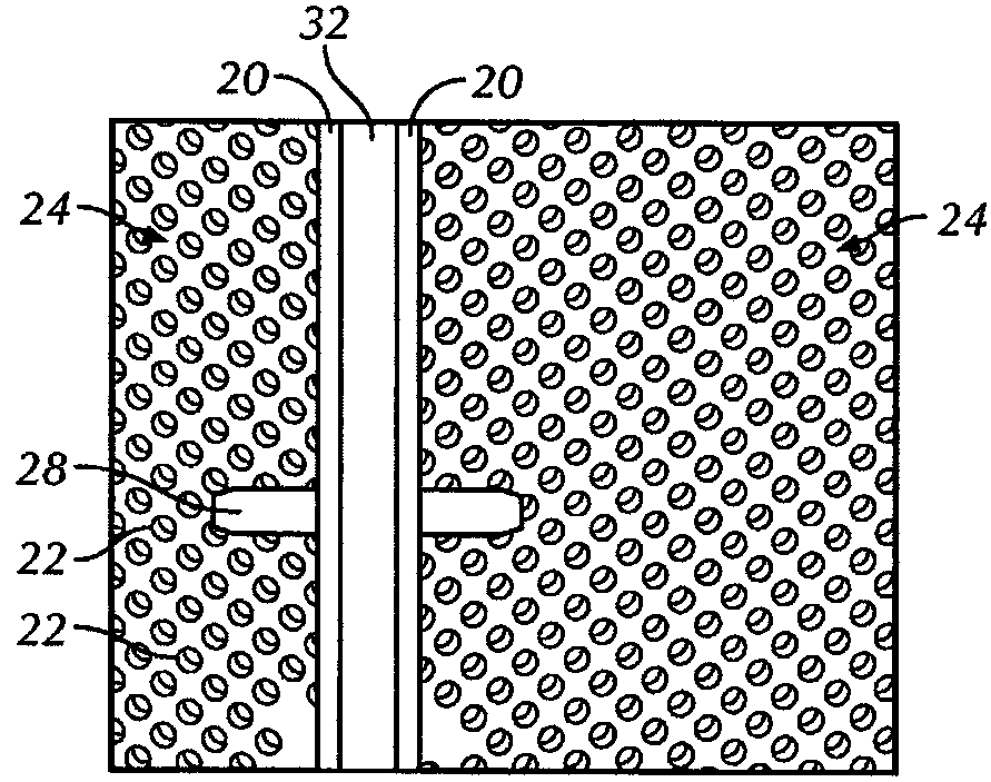
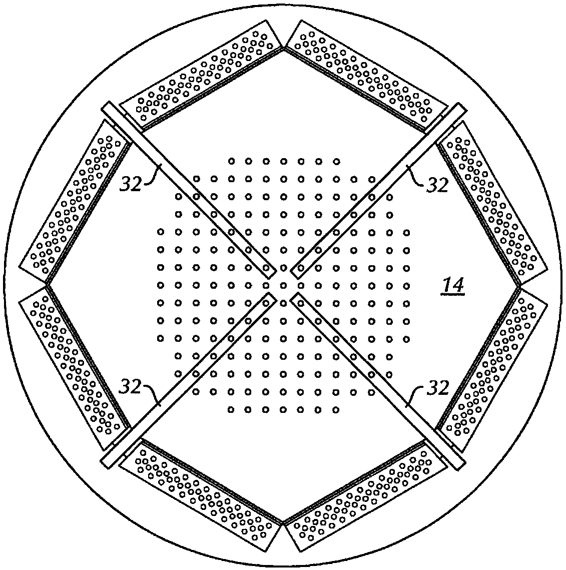
The present application relates to a flow distribution device. Embodiments in this application generally relate to distributing flow into a vessel containing a packed bed of media. Examples of applications of such beds are pressure swing or temperature swing adsorption systems. A system in the present application may include a container and a distributor for distributing flow to a lower portion of the container. The system may include: a vessel including a top head and a bottom head; and a bottom head infeed/outflow nozzle. A lower distributor having at least one flow admissible surface is arranged within the vessel and surrounds the inlet of the bottom head infeed/outflow nozzle. A flow gap is formed between a bottom portion of the lower distributor and the bottom head feed/outlet nozzle.

Description

technical field [0001] Embodiments disclosed herein relate generally to devices for distributing flow into containers. More specifically, embodiments disclosed herein relate to flow distribution devices for use in pressure swing or temperature swing adsorption systems. Background technique [0002] Pressure swing adsorption (PSA) is a technique for fractional distillation of a gas mixture to provide at least one mixture of purified product gas and raffinate by-products. PSA has been successfully used to separate hydrogen from other gases, oxygen and nitrogen from air, and helium from natural gas, among others. [0003] A PSA system may include a plurality of vessels containing adsorbents to separate the gases. The vessel may include top and bottom heads through which flow conduits or nozzles are arranged. [0004] During the PSA process, the adsorption vessel goes through various stages of the cyclic process, including feed, pressure equalization, product pressurization, ...

Claims


Application Information

Patent Timeline
IPC IPC(8): B01D53/047
CPCB01D53/047B01D53/0446B01D53/0462F15D1/02
Inventor 富兰克林·D·罗马克斯乔纳森·利维克里斯·埃贝林理查德·S·托德
Owner LUMMUS TECH INC
Learn More