Gate driver and its configuration system and adjustment configuration method

A gate driver and gate drive technology, applied in instruments, static indicators, etc., can solve the problems of unbalanced thrust, "split screen, different rising edge times of voltage pulse signals, etc., to avoid split screen phenomenon, balanced Good results

Active Publication Date: 2018-02-06
CHONGQING BOE OPTOELECTRONICS +1
View PDF3 Cites 0 Cited by
  • Summary
  • Abstract
  • Description
  • Claims
  • Application Information

AI Technical Summary

Problems solved by technology

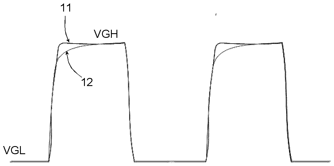
Delay due to wiring (e.g. RC (resistance-capacitance) delay) , will cause the rising edge times of the voltage pulse signals 11 and 12 to be significantly different, so that for different TFT array regions, the thrust of the drive control signal they receive is unbalanced
[0005] Therefore, for different TFT array areas, it is reflected that the thrust of the received drive control signal is unbalanced or inconsistent, that is, the time from VGL to VGH is different; this imbalance will cause " "Split screen" phenomenon (for example, it will be reflected in reliability tests such as low temperature of the display panel)
[0006] Of course, for the differences between different gate drivers, the thrust of the gate drive signal output between them is different, for example, even for the same type of chip produced by the same manufacturer, due to process fluctuations in semiconductor manufacturing, etc. The reason is that there are more or less differences in the thrust of the gate drive signal driven by its output. If the thrust difference of the gate drive signal is finally reflected on the drive control signal finally received by the TFT array area, it will also be affected by the difference in thrust. The split-screen phenomenon mentioned above occurs due to equalization

Method used


Image

  • Gate driver and its configuration system and adjustment configuration method
  • Gate driver and its configuration system and adjustment configuration method
  • Gate driver and its configuration system and adjustment configuration method

Examples


Embodiment Construction

[0052] The following introduces some of the possible embodiments of the present invention, which are intended to provide a basic understanding of the present invention, but are not intended to identify key or decisive elements of the present invention or limit the scope of protection. It is easy to understand that, according to the technical solution of the present invention, those skilled in the art may propose other alternative implementation manners without changing the essence and spirit of the present invention. Therefore, the following specific embodiments and drawings are only exemplary descriptions of the technical solution of the present invention, and should not be regarded as the entirety of the present invention or as a limitation or restriction on the technical solution of the present invention.

[0053] In this article, "gate drive signal" refers to the signal directly output by the gate driver to drive the TFT array area, which is not transmitted through external...


PUM


Abstract

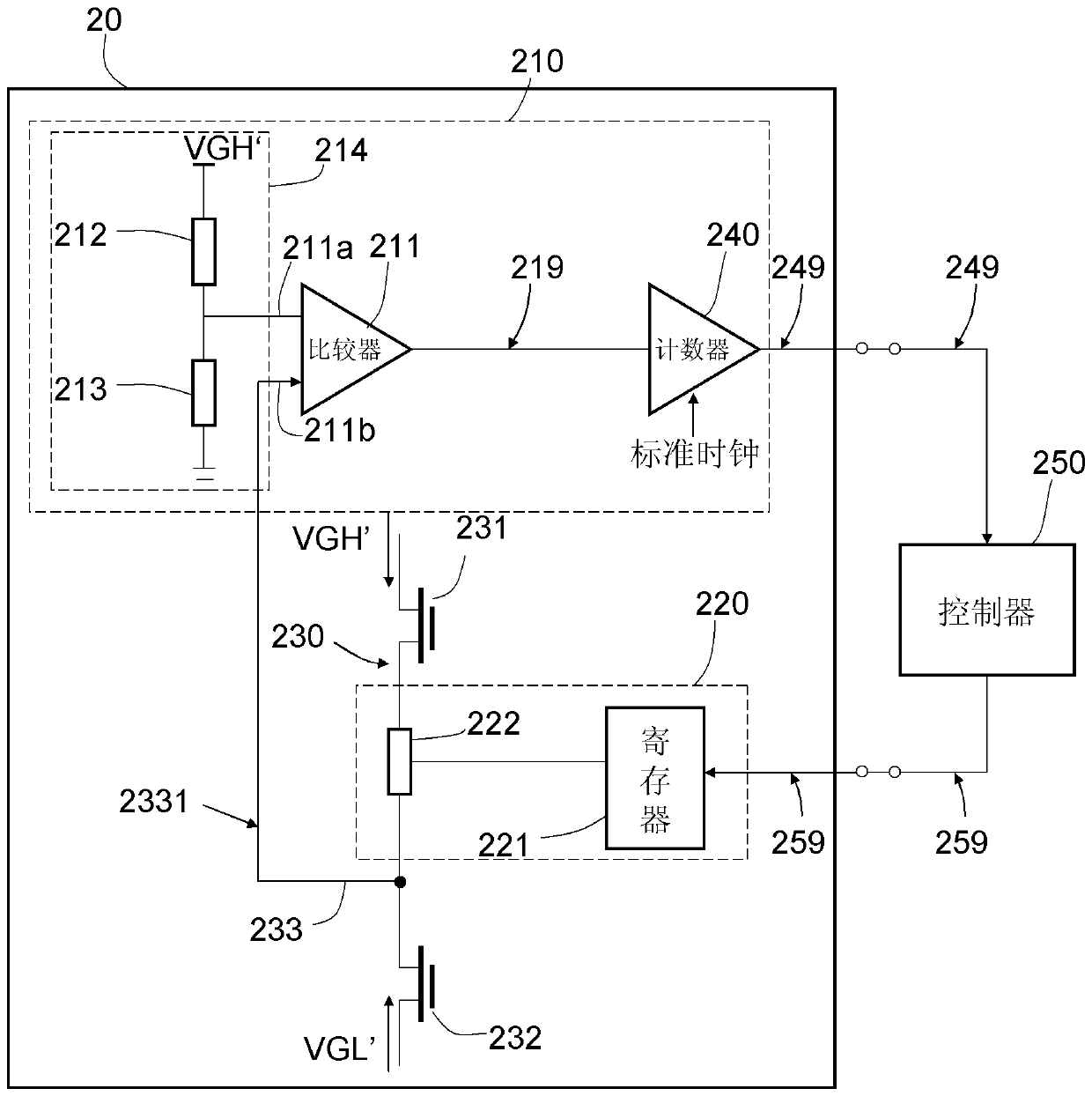
The invention provides a gate driver, a configuration system and an adjustment configuration method thereof, and belongs to the technical field of TFT array driving of a thin film transistor (TFT) display panel. The gate driver of the present invention is used to provide a gate drive signal for the TFT array substrate, which at least includes a thrust detection module and a thrust adjustment module, and the configuration system of the present invention is used to adjust and configure the thrust of multiple gate drivers, which includes A plurality of controllers provided externally to the gate drivers. The thrust of the gate driver of the present invention can be adjusted and configured, and the configuration system of the present invention adjusts and configures a plurality of gate drivers that are respectively corresponding to the drive control signals received by different TFT array regions. The balance of the thrust is good, Split screen phenomenon can be avoided.

Description

technical field [0001] The invention belongs to the technical field of TFT array driving of a thin film transistor (TFT) display panel, and relates to a gate driver for providing a gate drive signal for a TFT array substrate, in particular to a gate driver whose thrust of the output gate drive signal can be adjusted. A pole driver, a configuration system for configuring a plurality of gate drivers to equalize thrust among them, and an adjustment configuration method. Background technique [0002] In a thin film transistor liquid crystal display (TFT-LCD), a gate driver is required to drive and control the TFT array. As the resolution of TFT-LCD becomes higher and higher, the number of gate drivers that need to be used also increases; different gate drivers control different TFT array areas of the display panel, and the same gate driver also has different The fan-out end is used to drive different fan-out sub-regions of the TFT array region correspondingly driven by the gate...

Claims


Application Information

Patent Timeline
Patent Type & Authority Patents(China)
IPC IPC(8): G09G3/36
CPCG09G3/3696G09G2320/0223G09G3/3677G09G2310/08G09G2330/02
Inventor 高贤永许益祯肖利军侯帅徐波梁利生伏思庆尚飞邱海军
Owner CHONGQING BOE OPTOELECTRONICS
Why Eureka
Try Eureka