
Novel punching die for easy-to-tear films on polypropylene infusion bags
A punching die and polypropylene technology, applied in the direction of metal processing, etc., can solve the problems of affecting punching accuracy, reducing the punching efficiency of easy-tear film, affecting the production output of easy-tear film, etc., to improve punching efficiency and easy removal Easy to tear film and compact structure
- Summary
- Abstract
- Description
- Claims
- Application Information
AI Technical Summary
Problems solved by technology
Method used
Image

Examples
Embodiment Construction
[0014] The present invention will be further described below in conjunction with accompanying drawing, protection scope of the present invention is not limited to the following:
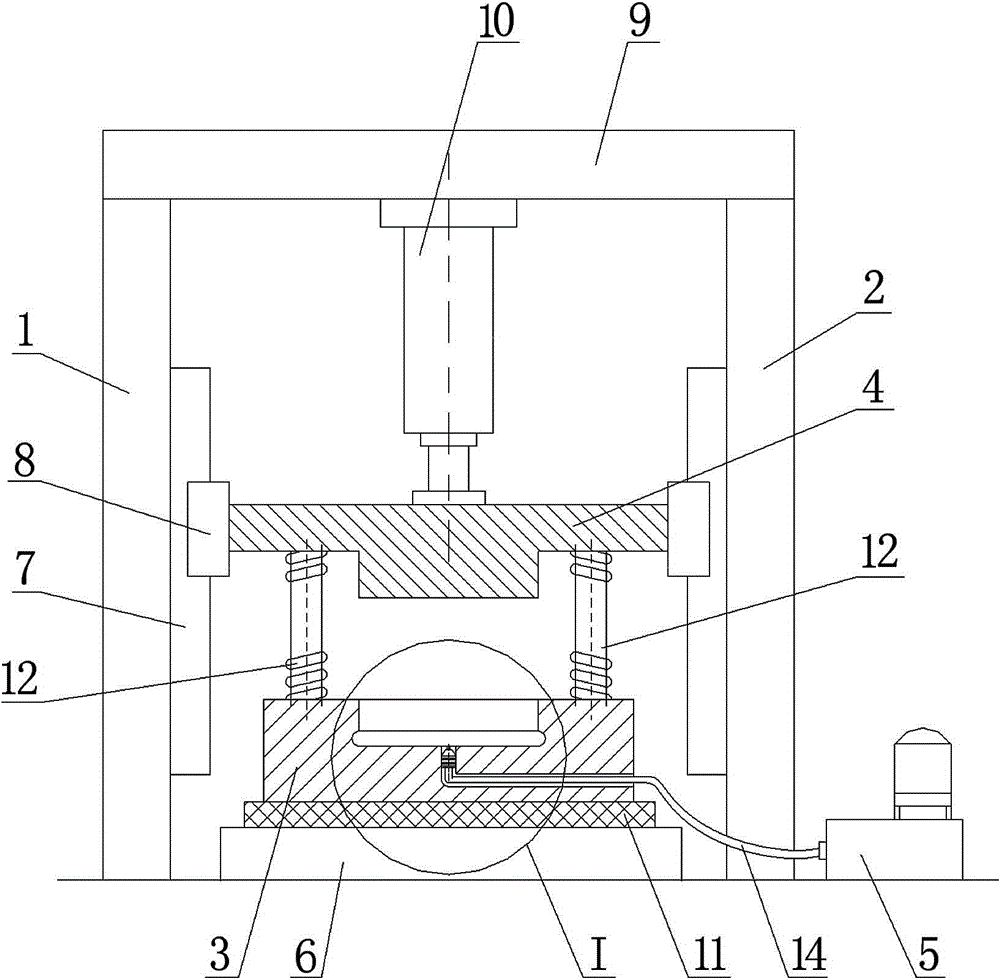
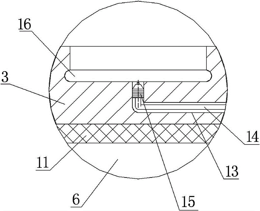
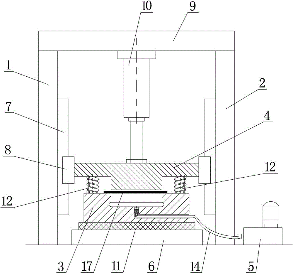
[0015] Such as figure 1 As shown, a die-cutting die for easy-tear film on a new type of polypropylene infusion bag, which includes a column I1, a column II2, a die 3, a punch 4, a constant pressure air source 5 and is arranged between the column I1 and the column II2 The workbench 6, the column I1 and the column II2 are vertically arranged, the guide rail 7 is arranged on the column I1 and the column II2, the slider 8 is installed on the two guide rails 7, and the supporting beam is arranged between the column I1 and the column II2 9. A cylinder 10 is fixedly installed on the bottom surface of the support beam 9. A punch 4 is arranged at the acting end of the piston rod of the cylinder 10. The left and right ends of the punch 4 are respectively fixed on two sliders 8. The guide rail 7 and the slider ...
PUM
 Abstract
Description
Claims
Application Information