Induction coil with dynamically variable coil geometry

An induction coil, variable technology, used in induction heating, coil installations, transformer/inductor coils/windings/connections, etc.

Active Publication Date: 2016-01-06
THERMATOOL
View PDF5 Cites 11 Cited by
  • Summary
  • Abstract
  • Description
  • Claims
  • Application Information

AI Technical Summary

Problems solved by technology

Fixed shape coils can only effectively weld

Method used


Image

  • Induction coil with dynamically variable coil geometry
  • Induction coil with dynamically variable coil geometry
  • Induction coil with dynamically variable coil geometry

Examples


Embodiment Construction

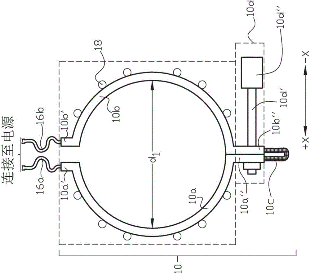
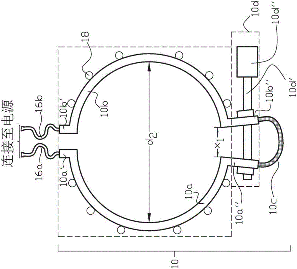
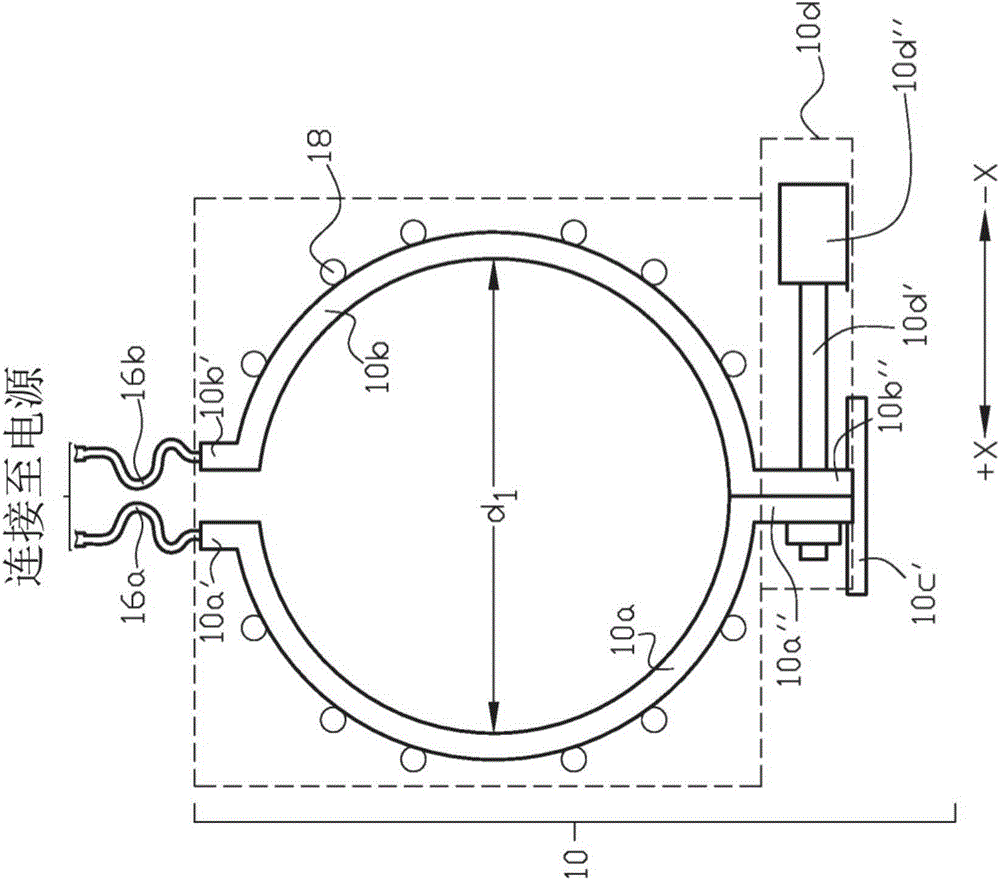
[0017] An example of a solenoid-type induction coil 10 having a dynamically variable coil shape is shown in diagrammatic cross-sectional FIGS. 1( a ) and 1 ( b ). The induction coil 10 is an at least one turn solenoid type coil comprising fixed inductive coil segments 10a and 10b and one or more adjustable coil segments 10c, each of which is combined with a separate adjustable coil segment assembly 10d connect.

[0018] The coil segments 10a and 10b are fixedly fixed along at least part of their coil segment lengths, or connected to the coil segments by elements. For example, as shown in the Figures, the power terminal ends 10a' and 10b' of the coil segments 10a and 10b may be securely secured adjacent to each other with space between the power terminals to provide electrical isolation between the power terminal ends. The space may be filled with an electrically insulating material, such as polytetrafluoroethylene or other suitable material. Optionally, flexible joints may b...


PUM


Abstract

A solenoidal induction coil with dynamically variable coil geometry is provided for inductively welding or heating continuous or discontinuous workpieces passing through the solenoidal induction coil in a process line. The coil geometry can change, for example, as the outer dimension of the workpiece passing through the solenoidal induction coil changes or as non-continuous workpieces pass through the solenoidal induction coil in an induction heating or welding process line.

Description

[0001] Cross References to Related Applications [0002] This application claims the benefit of US Provisional Application No. 61 / 823,035, filed May 14, 2013, which is hereby incorporated by reference in its entirety. technical field [0003] The present invention relates generally to electric induction welding or heating of workpieces within a solenoid-type induction coil, and more particularly to such induction welding or heating in which the outer dimensions of the workpiece can vary and the coil shape of the induction coil can be dynamically changed to accommodate the workpiece Variation in size. Background technique [0004] The workpiece can be passed through a solenoid-type induction coil to inductively weld or heat the workpiece. Fixed shape coils can only effectively weld or heat a limited size range of workpieces. [0005] It is an object of the present invention to provide apparatus and methods for electric induction welding or heating of workpieces passing thro...

Claims


Application Information

Patent Timeline
IPC IPC(8): H01F27/28H01F27/24
CPCH05B6/104H05B6/36H05B6/42
Inventor 托马斯·伊格纳托夫斯基迈克尔·A·纳伦
Owner THERMATOOL
Why Eureka
Try Eureka