Intelligent electronic sphygmomanometer control system and intelligent electronic sphygmomanometer control method

An electronic sphygmomanometer and control system technology, applied in medical science, sensors, diagnostic recording/measurement, etc., can solve problems such as single function, inability to realize positioning, and calling for help

Active Publication Date: 2016-01-27
SHENZHEN YUNHAI INTERNET OF THINGS TECH CO LTD
View PDF7 Cites 4 Cited by
  • Summary
  • Abstract
  • Description
  • Claims
  • Application Information

AI Technical Summary

Problems solved by technology

[0004] The purpose of the present invention is to overcome the deficiencies of the above-mentioned prior art, to provide an intelligent electronic sphygmomanometer control system and method capable of realizing positioning, calling for help, step counting and remote viewing of measurement results by mobile APP, aiming to solve the problem of existing electronic sphygmomanometer Due to the single function of the meter, it can only realize simple blood pressure measurement and heart rate measurement, but cannot realize the technical problems of functions such as positioning, calling for help, step counting and remote viewing of measurement results by smartphone APP.

Method used


Image

  • Intelligent electronic sphygmomanometer control system and intelligent electronic sphygmomanometer control method
  • Intelligent electronic sphygmomanometer control system and intelligent electronic sphygmomanometer control method
  • Intelligent electronic sphygmomanometer control system and intelligent electronic sphygmomanometer control method

Examples


Embodiment 1

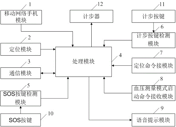
[0048] Such as figure 1 As shown, an intelligent electronic sphygmomanometer control system includes a mobile network mobile phone module 1, a positioning module 2, a communication module 3, a processing module 4, an SOS button detection module 5, a step counting button detection module 6, a positioning command receiving module 7, Blood pressure measurement mode start command receiving module 8 and voice prompt module 9;

[0049] The mobile network mobile phone module 1 is connected to the processing module 4 for providing mobile network support;

[0050] The positioning module 2 is connected with the processing module 4, and is used to obtain the current position information of the intelligent electronic sphygmomanometer;

[0051] The communication module 3 is connected with the processing module 4, and is used to establish a signal connection with one or more smart phone APPs associated with the smart electronic sphygmomanometer;

[0052] The SOS button detection module 5 ...

Embodiment 2

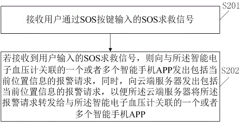
[0073] Such as figure 2 Shown, a kind of intelligent electronic sphygmomanometer control method, comprises the following steps:

[0074] S201, receiving an SOS distress signal input by the user through the SOS button;

[0075] S202. If the SOS distress signal input by the user is received, an alarm request including the current location information is sent to one or more smart phone APPs associated with the smart electronic blood pressure monitor, and at the same time, an alarm request including the current location information is sent to the cloud server. An alarm request, so that the cloud server forwards the alarm request to one or more smart phone APPs associated with the smart electronic sphygmomanometer.

[0076] In the embodiment of the present invention, there can be one smart phone associated with the smart electronic sphygmomanometer, or there can be multiple ones. In this way, one or more SOS numbers can be set, for example, three SOS numbers can be set for SOS wh...

Embodiment 3

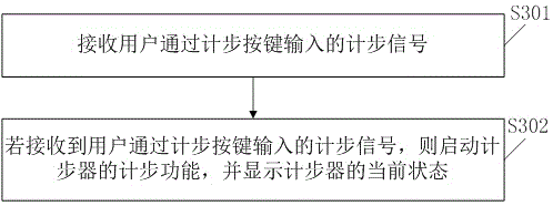
[0078] Such as image 3 As shown, a method for controlling an intelligent electronic sphygmomanometer also includes the following steps:

[0079] S301, receiving a pedometer signal input by the user through the pedometer button;

[0080] S302, if the step counting signal input by the user through the step counting button is received, start the step counting function of the pedometer, and display the current state of the pedometer.

[0081] The intelligent electronic sphygmomanometer control system provided by the embodiment of the present invention, when the pedometer button detection module detects that the pedometer button is pressed, generates a detection signal that detects that the pedometer button is pressed and sends it to the processing module, so that the processing module starts The step counting function of the pedometer, and display the current state of the pedometer, so as to realize the step counting function of the intelligent electronic blood pressure monitor....


PUM


Abstract

The invention discloses an intelligent electronic sphygmomanometer control system and an intelligent electronic sphygmomanometer control method. The system comprises a mobile network mobile phone module, a positioning module, a communication module, a processing module, an SOS key detection module, a positioning command receiving module, a blood pressure measurement mode starting command receiving module, a voice prompting module and a step calculation key detection module. The processing module is respectively connected with the mobile network mobile phone module, the positioning module, the communication module, the SOS key detection module, the positioning command receiving module, the blood pressure measurement mode starting command receiving module, the voice prompting module and the step calculation key detection module. The intelligent electronic sphygmomanometer control system is capable of realizing functions of positioning, calling for help, step calculation, remote measurement result checking with mobile phone APP, and the like.

Description

technical field [0001] The invention relates to the technical field of electronic sphygmomanometers, in particular to an intelligent electronic sphygmomanometer control system and method. Background technique [0002] Electronic sphygmomanometers use electronic pressure and pulsation sensors (instead of stethoscopes) to identify pressure and pulsation signals and express them in digital form. The upper part of the screen is the systolic blood pressure, and the lower part is the diastolic blood pressure and pulse rate. Its advantage is that it is easy to operate, the reading is intuitive, and the measurement will be carried out automatically just by pressing a button, which is suitable for home use. [0003] However, the existing electronic sphygmomanometer functions are too single, and can only realize simple blood pressure measurement and heart rate measurement, and cannot realize functions such as positioning, calling for help, step counting, and remote viewing of measurem...

Claims


Application Information

Patent Timeline
IPC IPC(8): A61B5/0225A61B5/00
Inventor 翟斌
Owner SHENZHEN YUNHAI INTERNET OF THINGS TECH CO LTD
Why Eureka
Try Eureka