Supercharge Your Innovation With Domain-Expert AI Agents!

Inkjet head, inkjet recording device and manufacturing method of vibration damping component

A manufacturing method and inkjet head technology, applied in printing and other directions, can solve the problems of loss of vibration damping effect, reduction of pressure wave attenuation efficiency, etc.

Active Publication Date: 2016-01-27
KONICA MINOLTA INC
View PDF10 Cites 4 Cited by
  • Summary
  • Abstract
  • Description
  • Claims
  • Application Information

AI Technical Summary

Problems solved by technology

However, if the thickness of the film is increased, the pressure wave attenuation efficiency will decrease, and there is a problem that the vibration damping effect will be impaired.

Method used


Image

  • Inkjet head, inkjet recording device and manufacturing method of vibration damping component
  • Inkjet head, inkjet recording device and manufacturing method of vibration damping component
  • Inkjet head, inkjet recording device and manufacturing method of vibration damping component

Examples


no. 1 approach

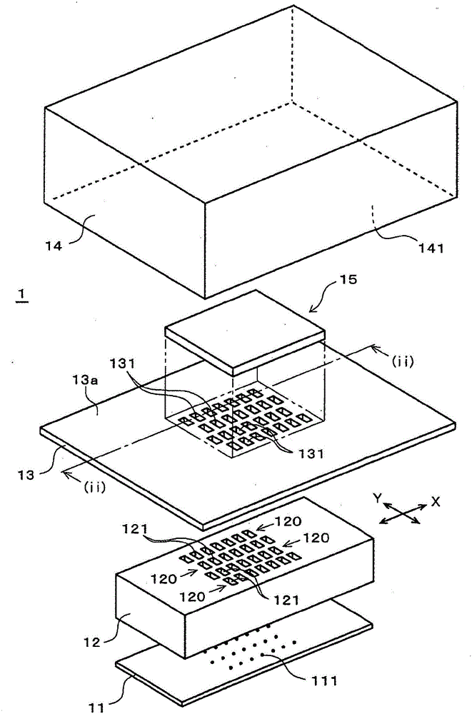
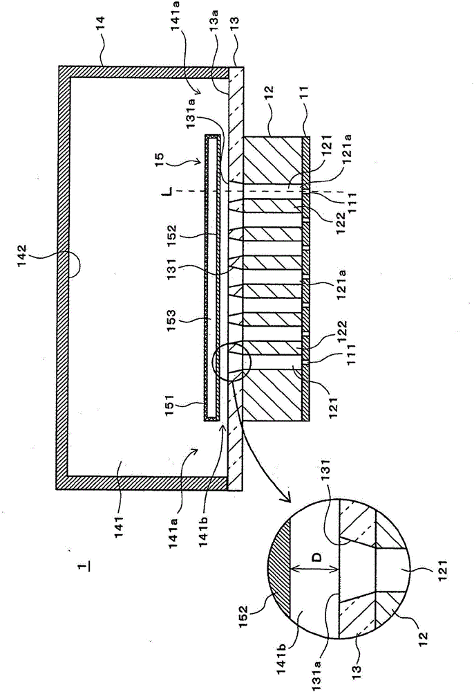
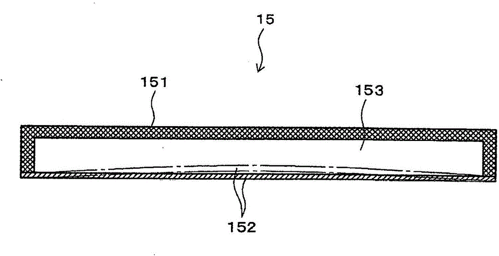
[0151] figure 1 It is an exploded perspective view showing an example of the first embodiment of the inkjet head of the present invention, figure 2 is along figure 1 The cross-sectional view of the inkjet head cut by the line (ii)-(ii), image 3 is a cross-sectional view of the damper.

[0152] Inkjet head 1 from figure 1 The nozzle plate 11 , the inkjet head chip 12 , the substrate 13 , and the ink manifold 14 are provided in this order from the lower part, and the inkjet head 1 is formed by bonding these components to each other. The damping member 15 is arranged inside the common ink chamber 141 formed by the inner space of the ink manifold 14 .

[0153] The inkjet head chip 12 shown in this embodiment has a hexahedron shape, and a plurality of pressure chambers 121 are arranged therein. Each pressure chamber 121 is formed so as to pass through in a straight line across the surface of the head chip 12 on the nozzle plate 11 side and the surface on the substrate 13 sid...


PUM


Abstract

The invention provides an inkjet head, an inkjet recording device and a manufacturing method of a vibration damping component. The inkjet head is provided with the components of pressure chambers which are arranged in more than two rows; a common ink chamber which is communicated with the pressure chambers through ink inlets of the pressure chambers; and a vibration damping component which is configured in the common ink chamber and is provided with a vibration damping frame and a flexible film. At least the surface, which faces the ink inlets, of the vibration damping frame is made of the flexible film. The pressure in a chamber which is composed of the vibration damping frame and the flexible film is negative.

Description

technical field [0001] The present invention relates to an inkjet head, an inkjet recording device, and a method for manufacturing a damping member, and in particular, to an inkjet head, an inkjet recording apparatus, and an inkjet recording apparatus capable of reducing the influence between columns of pressure chambers caused by crosstalk. Apparatus and method of manufacturing a vibration-damping component. Background technique [0002] Inkjet heads sometimes have uneven ejection performance due to pressure waves generated by driving. This is because a pressure wave generated in a pressure chamber by driving propagates to another pressure chamber communicated with a common ink chamber, and so-called crosstalk occurs in which the emission characteristics of the pressure chamber through which the pressure wave propagates fluctuates. [0003] Conventionally, as a technique for reducing the influence between pressure chambers caused by crosstalk, the following technique has b...

Claims


Application Information

Patent Timeline
Patent Type & Authority Applications(China)
IPC IPC(8): B41J2/14B41J2/01
Inventor 比江岛一树上田正人
Owner KONICA MINOLTA INC
Features
  • R&D
  • Intellectual Property
  • Life Sciences
  • Materials
  • Tech Scout
  • Unparalleled Data Quality
  • Higher Quality Content
  • 60% Fewer Hallucinations
Learn More