Mounting machine mounting angle adjustment method and system

A technology of angle adjustment and placement machine, which is applied in the direction of assembling printed circuits with electric components, can solve the problems of wasting electric energy, high cost, complicated wiring, etc., and achieve the effect of high efficiency, simple structure and cost saving

Active Publication Date: 2018-05-18
孔金寿
View PDF7 Cites 0 Cited by
  • Summary
  • Abstract
  • Description
  • Claims
  • Application Information

AI Technical Summary

Problems solved by technology

The nozzle angle adjustment mechanism is a very important mechanism in the ultra-high-speed placement machine. Since the ultra-high-speed placement machine generally has multiple suction nozzles, this increases the difficulty of designing the nozzle angle adjustment mechanism. If the nozzle angle adjustment Poor mechanism design will directly affect the work efficiency and processing cost of the placement machine
[0004] The traditional high-speed placement machine nozzle adjustment mechanism mainly uses m motors to control the rotation of m nozzles respectively. The disadvantage of this method is that the motion control integration is more troublesome, and each motor must rotate with the corresponding nozzle, so the wiring Complicated and wastes power
The second is to use a motor to drive a friction wheel to rotate, and then let the friction wheel drive m suction nozzles to adjust the angle. The disadvantage of this method is that a circular grating ruler needs to be installed on each suction nozzle, which is costly and When adjusting the angle, the movement of other parts of the placement head should be stopped to allow the friction wheel pair to approach, which increases the time for one cycle of placement of the placement machine

Method used


Image

  • Mounting machine mounting angle adjustment method and system
  • Mounting machine mounting angle adjustment method and system
  • Mounting machine mounting angle adjustment method and system

Examples


Embodiment Construction

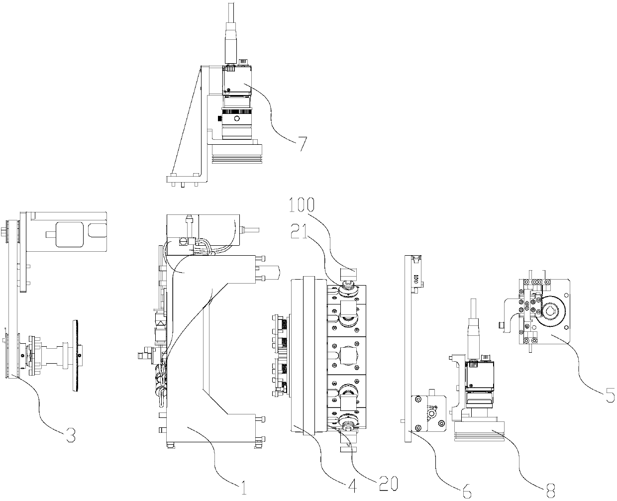
[0036] figure 1 It shows a mounter mounting angle adjustment system in a preferred embodiment of the present invention, the mounter mounting angle adjustment system includes a support frame 1, a suction nozzle plate 20, a plurality of suction nozzles 21, for adjusting multiple The first drive mechanism 3 for the patch angle of the suction nozzle 21, the second drive mechanism 4 for driving the rotation of the suction nozzle plate 20, and the second drive mechanism 4 for driving the suction nozzle 21 to move relative to the suction nozzle plate 20 along the central axis of the suction nozzle 21 The third driving mechanism 5, the first camera 7 for photographing the deflection angle of the component 100 sucked by the suction nozzle 21, the second camera 8 for photographing the circuit board to be mounted, and a camera for covering the supporting frame 1 on the cover plate 6. Both the first driving mechanism 3 and the second driving mechanism 4 are installed on the support frame...


PUM


Abstract

The invention provides a mounting angle adjustment method and system of a placement machine, which includes a plurality of suction nozzles for absorbing and mounting components, a suction nozzle plate for installing the plurality of suction nozzles, and a suction nozzle plate for driving each The suction nozzle rotates around its central axis to adjust the first drive mechanism for patch angle, and the second drive mechanism for driving the suction nozzle coil to rotate around its central axis. The first drive mechanism includes a first gear, a drive unit and a plurality of gear sets, each of the gear sets is respectively correspondingly connected to one of the suction nozzles, and the driving unit is used to drive the first gear to rotate to drive each of the gear sets, so that each of the The gear sets respectively drive the corresponding suction nozzles to rotate around their central axes. The invention has the beneficial effects of simple structure, cost saving and higher efficiency.

Description

technical field [0001] The invention relates to surface mount technology, in particular to a method and system for adjusting the mount angle of a mounter. Background technique [0002] Surface mount technology (Surface Mounting Technology, referred to as SMT) refers to the direct soldering of surface mount components (also known as chip components, such as IC, capacitors, resistors, etc.) Mounting technology on the specified position on the surface of the board. Applying surface mount technology to electronic products not only makes the products highly reliable and has more functions, but also makes the products gradually lighter and smaller. The long-term development has made today's SMT technology gradually mature, and it has been widely used in various fields such as manufacturing, computer industry and communication industry. The placement machine is the most important equipment on the SMT production line, and the performance of the placement machine directly affects t...

Claims


Application Information

Patent Timeline
Patent Type & Authority Patents(China)
IPC IPC(8): H05K3/30
Inventor 孔金寿
Owner 孔金寿
Why Eureka
Try Eureka