Device for machining workpieces

A technology for processing workpieces and driving devices, which is applied in the field of devices for processing workpieces, and can solve the problems that the outer diameter and inner diameter cannot be processed, and the diameter range cannot be processed.

Inactive Publication Date: 2015-03-11
海科特有限公司
View PDF8 Cites 0 Cited by
  • Summary
  • Abstract
  • Description
  • Claims
  • Application Information

AI Technical Summary

Problems solved by technology

Machining of outer and inner diameters is not possible with this solution
[0005] Further...

Method used


Image

  • Device for machining workpieces
  • Device for machining workpieces
  • Device for machining workpieces

Examples


Embodiment Construction

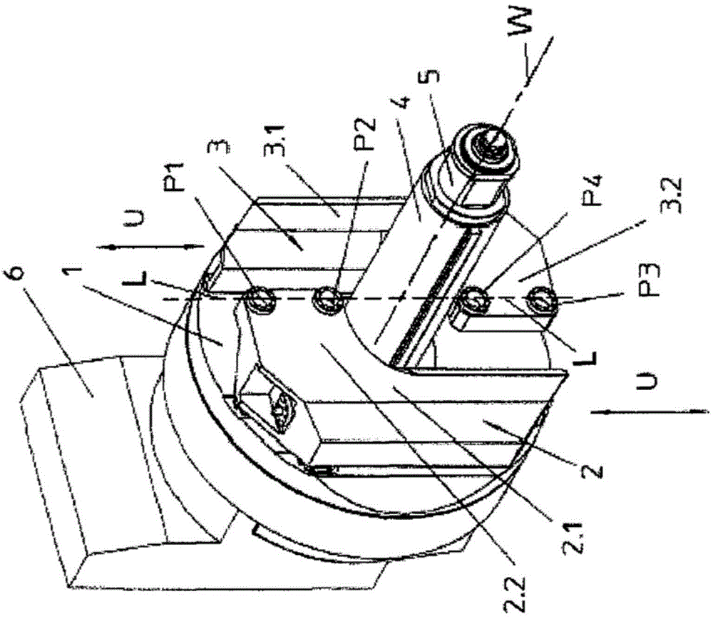
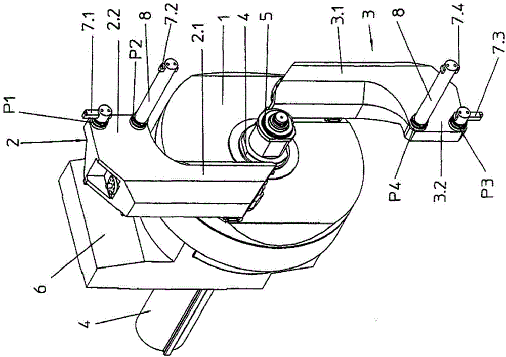
[0036] exist figure 1 shows a device according to the invention with a faceplate 1 on which a first cross slide 2 and a second cross slide 3 are arranged in a radially inwardly displaced end position. The rectilinear and mutually parallel adjustability of the cross slides 2 and 3 along the respective longitudinal axes U is achieved via linear guides not shown here. Faceplate 1 is rotatable around a rotation axis W and by means of a column (see Figure 11 ) is linearly movable along a Z axis Z, which extends parallel to the axis of rotation W. one in figure 1 The working spindle 5 of the horizontal machining center not shown in the figure protrudes through the face plate 1 and the cross tool rest 4 . The faceplate 1 is fixed by means of a guide 6 .

[0037] The first cross-slide 2 has a guide area 2.1 from which an angled arm 2.2 extends in the direction of the second cross-slide 3. FIG. A first tool receptacle P1 for a first tool and a second tool receptacle P2 for a seco...


PUM


Abstract

A device for machining workpieces, in which a surface plate (1) that can be driven about a rotational axis (W) can be moved in a linear fashion along the rotational axis (W) and the rotational axis (W) is constructed as a hollow axis (H), on the outside diameter of which the surface plate is rotatably mounted, and in which two cross slides (2, 3) which can be displaced radially to the outside and inside perpendicular to the rotational axis (W) are provided on the surface plate (1), and in which the surface plate (1) can be driven by a first drive and the cross slides (2, 3) can be driven by a common second drive.

Description

[0001] This application is a divisional case of the original application with the filing date of February 24, 2010, the application number 201080009324.1 (the international application number is PCT / DE2010 / 075018), and the title of the invention is "A device for processing workpieces". technical field [0002] The invention relates to a device for machining workpieces, in which a face plate drivable about a rotational axis and a cross slide arranged thereon are provided. Background technique [0003] Known from DE 39 41 783 C2 is a machine tool for cyclic milling of circular contours, which has a milling spindle support or a plurality of milling spindle supports which are radially adjustable to the diameter of the workpiece, which via a The gear transmission and each planetary gear can be driven. In particular, two milling cutters are fixed on each horizontal spindle. The two spindles are mounted on a slide which is arranged radially displaceable in radial guides, whereby t...

Claims


Application Information

Patent Timeline
IPC IPC(8): B23B29/034
CPCY10T408/8598Y10T82/125B23B2270/16B23B29/03439Y10T82/2529Y10T82/22
Inventor A·波尼施D·施利德
Owner 海科特有限公司
Why Eureka
Try Eureka