
Regulating mechanism for positioning manipulator

A technology of adjusting mechanism and manipulator, applied in manipulators, program-controlled manipulators, manufacturing tools, etc., can solve the problems of inability to detect batteries, low production efficiency, time-consuming and labor-intensive, etc. Effect

Inactive Publication Date: 2018-10-09
JINGDE COUNTY HANHAI NEBULA INTELLIGENTIZE TECH RES & DEV CO LTD
View PDF4 Cites 0 Cited by
  • Summary
  • Abstract
  • Description
  • Claims
  • Application Information

AI Technical Summary

Problems solved by technology

When testing lithium batteries, the tray needs to be placed in the testing equipment to test the lithium battery, but the volume of the battery slot in the tray is larger than the volume of the lithium battery to be tested, and the position of the lithium battery in the battery slot is not fixed , This will cause the probe of the detection equipment to sometimes not touch the battery, so that the battery cannot be tested. This requires moving the lithium battery to a suitable position to ensure the normal detection. The traditional way is to move it manually , not only time-consuming and labor-intensive, but also low production efficiency

Method used


Image

  • Regulating mechanism for positioning manipulator
  • Regulating mechanism for positioning manipulator
  • Regulating mechanism for positioning manipulator

Examples


Embodiment Construction

[0021] The following will clearly and completely describe the technical solutions in the embodiments of the present invention with reference to the accompanying drawings in the embodiments of the present invention. Obviously, the described embodiments are only some, not all, embodiments of the present invention.

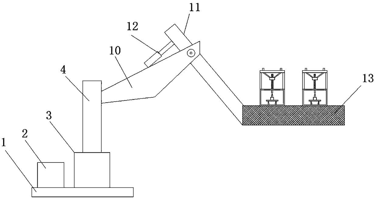
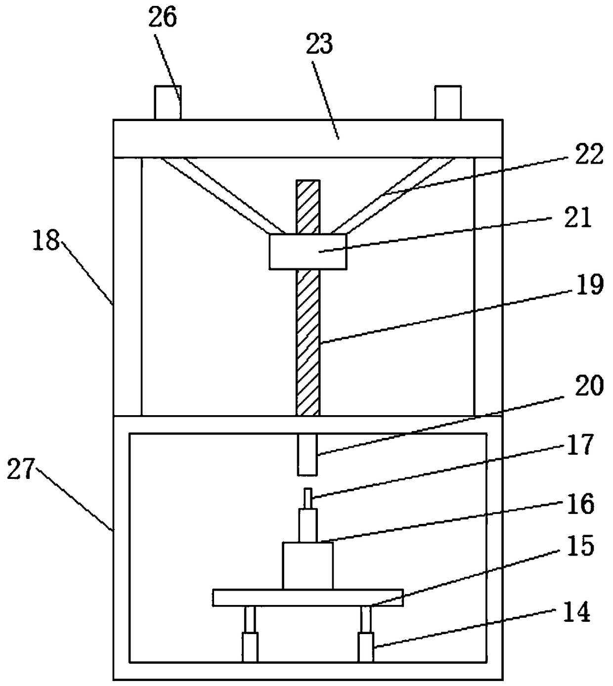
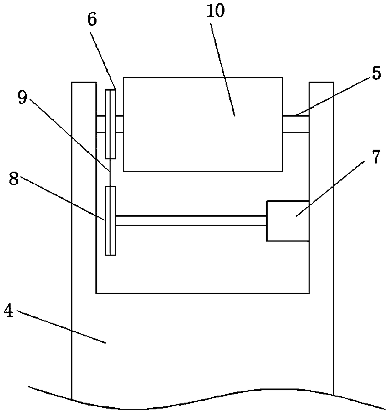
[0022] refer to Figure 1-5 , an adjustment mechanism for positioning the manipulator, including a base 1, a control box 2 and a rotating base 3 are installed on the upper surface of the base 1, a supporting column 4 is connected to the rotating base 3, and a groove is provided on the top of the supporting column 4. Rotating shaft 5 is installed between the two side walls of the groove, the rotating seat 3 is a rectangular cavity structure, a rotating motor is installed on the bottom inner wall of the rotating seat 3, and the output shaft of the rotating motor runs through the top side wall of the rotating seat 3 Connected with support column 4, first belt pulley 6 i...


PUM


Abstract

The invention discloses a regulating mechanism for a positioning manipulator. The regulating mechanism comprises a base; a control box and a rotating seat are mounted on the upper surface of the base,and a supporting column is connected with the rotating seat; a groove is formed in the top of the supporting column, and a rotating shaft is rotatably mounted between the two side walls of the groove; a first belt pulley is mounted outside the rotating shaft, and a first motor is mounted on the side wall of the groove; a second belt pulley is connected with an output shaft of the first motor, a belt is connected between the first belt pulley and the second belt pulley; and a large arm is mounted on the rotating shaft, a small arm is mounted at one end of the large arm rotatably, a first cylinder is mounted on the side wall of the large arm, and the small arm is connected with an output shaft of the first cylinder. The regulating mechanism is simple in structure and novel in design, adjusts the angle and direction of the positioning manipulator conveniently, relieves the operating burden of operators, further improves the accuracy of positioning, can position lithium batteries with different sizes, and is high in applicability and worth popularizing.

Description

technical field [0001] The invention relates to the technical field of adjustment mechanisms, in particular to an adjustment mechanism for positioning a manipulator. Background technique [0002] After the lithium battery is processed, it needs to be put into the battery slot in the tray for storage. There are generally two rows of battery slots in the tray, and one lithium battery is placed in each battery slot. When testing lithium batteries, the tray needs to be placed in the testing equipment to test the lithium battery, but the volume of the battery slot in the tray is larger than the volume of the lithium battery to be tested, and the position of the lithium battery in the battery slot is not fixed , This will cause the probe of the detection equipment to sometimes not touch the battery, so that the battery cannot be tested. This requires moving the lithium battery to a suitable position to ensure the normal detection. The traditional way is to move it manually , not ...

Claims


Application Information

Patent Timeline
Patent Type & Authority Applications(China)
IPC IPC(8): B25J9/02B25J9/10
CPCB25J9/02B25J9/104
Inventor 彭小宝
Owner JINGDE COUNTY HANHAI NEBULA INTELLIGENTIZE TECH RES & DEV CO LTD
Learn More