Tracked chassis for agricultural machinery

A crawler type and crawler technology, applied in the field of supporting chassis, can solve the problems of unsafe, difficult, and can not reach the height of the chassis frame of the deep mud paddy field machine from the ground, etc., and achieve the effect of smooth operation and prolonging the service life.

Inactive Publication Date: 2017-07-07
贺炳松
View PDF9 Cites 0 Cited by
  • Summary
  • Abstract
  • Description
  • Claims
  • Application Information

AI Technical Summary

Problems solved by technology

[0005] Second, in response to the problems mentioned in one of the above, there is a structure with a middle-drive triangular track configuration, but this structure is also an internal tension structure of the driving wheel, that is, the driving wheel is installed on the upper side of the track in the middle of the chassis frame to drive the track , although the chassis frame can properly raise some heights from the ground, but in addition to the common defects of the known front (or rear) internal drive type, there are also defects: The installation position of other components is limited, the center of gravity of the machine must be raised, the stability is relatively poor, which brings unsafe factors, and it still cannot meet the needs of the height of the machine chassis from the ground for paddy fields with deep mud feet
[0010] Seventh, according to my country's national conditions, grain production in hills and mountainous areas is absolutely indispensable at present, and small-sized wheeled harvesters are also needed for planting one-season rice and wheat. If the crawler walking is replaced by rubber wheels, loading and unloading is very difficult and quite troublesome

Method used


Image

  • Tracked chassis for agricultural machinery
  • Tracked chassis for agricultural machinery
  • Tracked chassis for agricultural machinery

Examples


Embodiment Construction

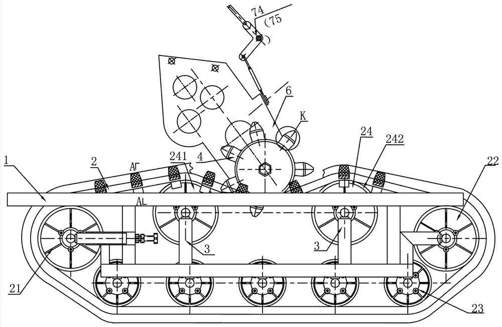
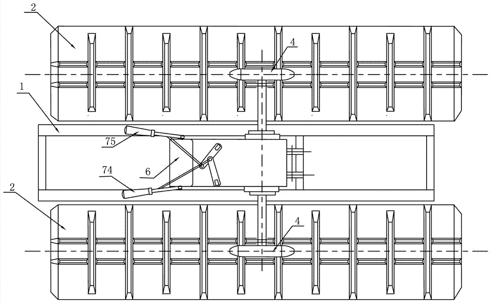
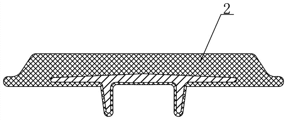
[0035] Such as Figure 1-Figure 10 As shown, a crawler chassis for agricultural machinery of the present invention includes a chassis frame 1, one side of the chassis frame 1 is connected to the left annular crawler structure, and the other side is connected to the right annular crawler structure, and the left and right annular crawler structures It is arranged symmetrically, and the left and right endless track structures respectively include an endless track 2 . The endless crawler belt 2 is provided with a driven wheel set consisting of a front pulley 21, a rear pulley 22, a bottom pulley 23 and a top pulley 24, wherein the top pulley 24 is a front top pulley 241 and a rear top pulley 242. , and the front and rear top pulleys 241, 242 are located at the inner top of the endless track 2 and hold the endless track 2 upwards, and a driving wheel 4 is engaged with the outer top of the endless track 2, and the driving wheel 4 is located at the top of the front and rear top belts...


PUM


Abstract

A crawler chassis used for agricultural machinery, the two sides of the chassis frame are respectively connected with left and right annular crawler structures, the left and right annular crawler structures respectively include a circular crawler, and the annular crawler is equipped with front, rear and bottom belts. A driven wheel set consisting of two pulleys and two top pulleys, and the top pulley is located at the top of the inner side of the endless track and supports the endless track upwards, and a driving wheel is engaged with the top of the outer side of the endless track, and the driving wheel is located at the supporting position of the two top pulleys between them and press the ring track from top to bottom, so that the ring track forms an arc shape on the top to meet the transmission wrap angle of the outer teeth of the driving wheel; two legs are respectively set on both sides of the chassis frame to support the left and right ring track structures. Two top pulleys, adjusting the height of the feet can realize the height adjustment of the chassis frame; a speed change gearbox is arranged between the left and right ring track structures, and the output shafts of the speed change gear box are respectively connected to the drive wheels of the left and right ring track structures , and can achieve 90% of agricultural machinery. Turn in place or 180. U-turn on the spot.

Description

technical field [0001] The invention relates to a crawler-type mechanical chassis, in particular to a crawler-type paddy field, dry soil cultivator, crawler-type rotary tiller, crawler-type tractor, and crawler-type combine harvester which are suitable for use in rural areas. Background technique [0002] The existing known crawler paddy fields, dry soil tillage machines, crawler rotary tillers, crawler tractors, crawler combine harvesters and other agricultural machinery (hereinafter referred to as agricultural machinery) all use ring-shaped rubber crawlers, and the supporting driving wheels The drive structure is all crawler internal tension type front or rear drive structure. The "track internal tension type front or rear drive structure" mentioned here means that the output shaft of the transmission gearbox and the driving wheel are installed at the front or rear position of the inner ring of the track, and the track is driven by the driving wheel to achieve the purpose ...

Claims


Application Information

Patent Timeline
Patent Type & Authority Patents(China)
IPC IPC(8): B62D55/08B62D55/12B62D55/14B62D11/00
Inventor 贺炳松
Owner 贺炳松
Why Eureka
Try Eureka