

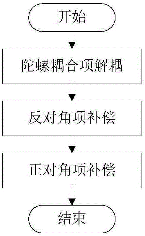
Modal decoupling decentralized control method used for magnetic bearing
A decentralized control, magnetic bearing technology, applied in general control systems, adaptive control, control/regulation systems, etc., can solve problems such as inability to suppress gyro coupling, achieve good decoupling effect and improve stability.
- Summary
- Abstract
- Description
- Claims
- Application Information
AI Technical Summary
Problems solved by technology
Method used
Image

Examples
Embodiment Construction
[0050] In order to facilitate the understanding of the modal decoupling decentralized control method for magnetic bearings provided by the present invention, firstly, the mathematical model of the magnetic bearing system can be obtained according to the rotor dynamics theory:
[0051] M q ·· c + G q · c + T L K s T L T q c = T L K i i - - - ( 1 - 1 )
[0052] M = m 0 ...
PUM
 Abstract
Description
Claims
Application Information