
A rotatable LED light

A technology for LED lamps and rotary adjustment, which is applied to parts of lighting devices, semiconductor devices of light-emitting elements, cooling/heating devices of lighting devices, etc. Simple, fast and safe to use

Active Publication Date: 2018-05-15
安徽金晟达生物电子科技有限公司
View PDF4 Cites 0 Cited by
  • Summary
  • Abstract
  • Description
  • Claims
  • Application Information

AI Technical Summary

Problems solved by technology

[0002] At present, LED lights used in some specific fields are generally fixed by screws and brackets. After installation and fixing, the LED lights can only illuminate in a fixed direction and cannot be changed. If you need to adjust the irradiation direction of LEDs, etc., you must use tools to readjust them. The installation is fixed, and the adjustment process is cumbersome, which brings inconvenience to the use

Method used


Image

  • A rotatable LED light

Examples


Embodiment Construction

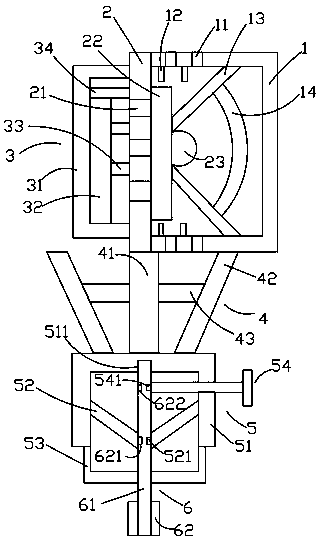
[0019] Such as figure 1 As shown, the rotatably adjustable LED of the present invention includes a lens 1, a base plate 2 located on the left side of the lens 1, a power supply device 3 located on the left side of the base plate 2, a support device 4 located below the base plate 2, and a base plate located on the left side of the base plate 2. The rotating device 5 below the supporting device 4 and the gripping device 6 located below the rotating device 5 .

[0020] Such as figure 1 As shown, the lens 1 is a hollow cuboid, the cross section of the lens 1 is concave, the left surface of the lens 1 is fixedly connected with the right surface of the bottom plate 2, and the lens 1 is provided with The first through hole 11 on the surface, the heat conducting sheet 12 inside, the reflector 13 and the curved mirror 14 arranged on the reflector 13 . The first through holes 11 are provided with several and are located on the upper and lower surfaces of the lens 1 respectively, the f...


PUM


Abstract

An LED lamp capable of being adjusted in a rotary mode comprises a lens (1), a bottom plate (2), a power device (3), a supporting device (4), a rotating device (5) and a holding device (6). The lens (1) is provided with first through holes (11), heat conduction fins (12), a reflection hopper (13) and a bent mirror (14). The bottom plate (2) is provided with second through holes (21), a circuit board (22) and an LED lamp bead (23). The power device (3) comprises a first frame body (31), a power source (32), first fixing rods (33) and a second fixing rod (34). The supporting device (4) comprises a first supporting rod (41), a supporting column (42) and first horizontal rods (43). The rotating device (5) comprises a rotating frame (51), third fixing rods (52), fourth fixing rods (53) and a locating rod (54). The holding device (6) comprises a holding rod (61) and a holding ring (62). According to the LED lamp, the irradiation direction of the LED lamp can be freely adjusted, and therefore the operation is easy, convenient and fast.

Description

technical field [0001] The invention relates to the technical field of LEDs, in particular to a rotatably adjustable LED lamp. Background technique [0002] At present, LED lights used in some specific fields are generally fixed by screws and brackets. After installation and fixing, the LED lights can only illuminate in a fixed direction and cannot be changed. If you need to adjust the irradiation direction of LEDs, etc., you must use tools to readjust them. The installation is fixed, and the adjustment process is cumbersome, which brings inconvenience to use. [0003] Therefore, it is necessary to provide a new technical solution to solve the above technical problems. Contents of the invention [0004] The object of the present invention is to provide a rotatably adjustable LED lamp that can effectively solve the above technical problems. [0005] In order to solve the above technical problems, the present invention adopts the following technical solutions: [0006] A ...

Claims


Application Information

Patent Timeline
Patent Type & Authority Patents(China)
IPC IPC(8): F21K9/20F21V13/04F21V14/00F21V23/06F21V29/503F21Y115/10
CPCF21V13/04F21V14/00F21V23/06
Inventor 不公告发明人
Owner 安徽金晟达生物电子科技有限公司
Learn More