Supercharge Your Innovation With Domain-Expert AI Agents!

A rotating vacuum airtight fixture

A technology of vacuum air and fixtures, which is applied in the direction of clamping, manufacturing tools, metal processing machinery parts, etc., and can solve problems such as vacuum pump connections

Active Publication Date: 2018-09-14
NANJING UNIV OF INFORMATION SCI & TECH
View PDF11 Cites 0 Cited by
  • Summary
  • Abstract
  • Description
  • Claims
  • Application Information

AI Technical Summary

Problems solved by technology

However, due to the existence of residual magnetism, the former is subject to certain restrictions in some applications. Relatively speaking, vacuum chucks are more advantageous in this respect.
[0003] However, due to the processing on the rotary machine tool, the vacuum pump cannot be connected with the fixture all the time during the processing of the parts. Therefore, air tightness has become a very important indicator for this type of furniture.

Method used


Image

  • A rotating vacuum airtight fixture
  • A rotating vacuum airtight fixture
  • A rotating vacuum airtight fixture

Examples


Embodiment Construction

[0015] The invention will be further described below with reference to the accompanying drawings.

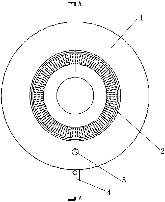
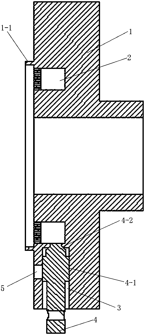
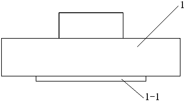
[0016] This embodiment adopts the combination of cylindrical surface and conical surface to seal, as shown in the attached Figure 1-3 As shown in the figure, a rotary vacuum airtight fixture is characterized in that: it comprises a main body 1 connected with a machine tool and a suction cup 2 arranged on the main body, the main body 1 is a hollow stepped cylinder, and the suction cup 2 is coaxial with the main body 1 The body 1 is provided with a radial air hole 3 that communicates with the suction cup 2, the radial air hole 3 is provided with an axial air suction hole 5, and the radial air hole 3 is provided with a valve that seals with the radial air hole 3. Core 4.

[0017] further:

[0018] A cylindrical seal 4-1 is provided between the valve core 4 and the radial air hole 3 .

[0019] A conical surface seal 4-2 is provided between the valve core 4 and the radial air hol...


PUM


Abstract

A rotating vacuum airtight clamp is characterized by comprising a body connected with a machine tool and a suction cup arranged on the body. The body is a hollow stepped cylinder. The suction cup is an inwards-concave circular ring coaxial with the body. The body is provided with a radial air vent communicated with the suction cup. The radial air vent is provided with an axial extractor vent. A valve element is arranged in the radial air vent, and the valve element and the radial air vent are sealed. Parts are adsorbed onto the rotating vacuum airtight clamp due to negative pressure, and moreover, the negative pressure can be maintained for a longer time by adopting the method that a conical surface and a cylindrical surface are combined in a sealed mode.

Description

technical field [0001] The invention relates to a rotary vacuum airtight clamp, which belongs to the technical field of clamps. Background technique [0002] In actual processing, some parts with special shapes are often encountered. The characteristics of these parts are that they are difficult to clamp, and it is difficult to clamp them by conventional mechanical methods, and special methods are often required to clamp them ( For example, the electromagnetic chuck is used for clamping, the vacuum chuck is used for clamping, etc.), as the name suggests, the electromagnetic chuck uses electromagnetic suction to clamp the workpiece to be processed, while the vacuum chuck uses the principle of negative pressure to clamp the workpiece. However, the former is limited in some applications due to the phenomenon of remanence. Relatively speaking, the vacuum chuck has more advantages in this regard. [0003] However, due to the machining on a rotary machine tool, the vacuum pump ca...

Claims


Application Information

Patent Timeline
Patent Type & Authority Patents(China)
IPC IPC(8): B23Q3/08
CPCB23Q3/088
Inventor 袁安富
Owner NANJING UNIV OF INFORMATION SCI & TECH
Features
  • R&D
  • Intellectual Property
  • Life Sciences
  • Materials
  • Tech Scout
  • Unparalleled Data Quality
  • Higher Quality Content
  • 60% Fewer Hallucinations
Learn More