Supercharge Your Innovation With Domain-Expert AI Agents!

Regenerative control device for hybrid vehicles

一种混合动力车辆、再生控制的技术,应用在混合动力车辆、动力装置、控制装置等方向,能够解决产生再生制动力等问题

Active Publication Date: 2017-11-24
MITSUBISHI MOTORS CORP
View PDF7 Cites 0 Cited by
  • Summary
  • Abstract
  • Description
  • Claims
  • Application Information

AI Technical Summary

Problems solved by technology

[0010] Although there is a technique of generating regenerative braking force even in a situation where battery charge is limited as disclosed in JP-A-2012-6525 and JP-A-2010-247749, there is a problem that, as in JP-A-2010-247749 - In the related art disclosed in A-2014-128075, when the regenerative level is set by the driver, it is difficult to generate the regenerative braking force according to the setting even while charging is restricted

Method used


Image

  • Regenerative control device for hybrid vehicles
  • Regenerative control device for hybrid vehicles
  • Regenerative control device for hybrid vehicles

Examples


Embodiment Construction

[0025] Hereinafter, preferred embodiments of a regeneration control device for a hybrid vehicle according to the present invention will be described in detail with reference to the accompanying drawings.

[0026] (Example)

[0027]

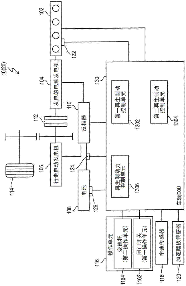
[0028] figure 1 is an explanatory view showing the structure of a hybrid vehicle 20 mounted with the regeneration control device 10 according to the embodiment.

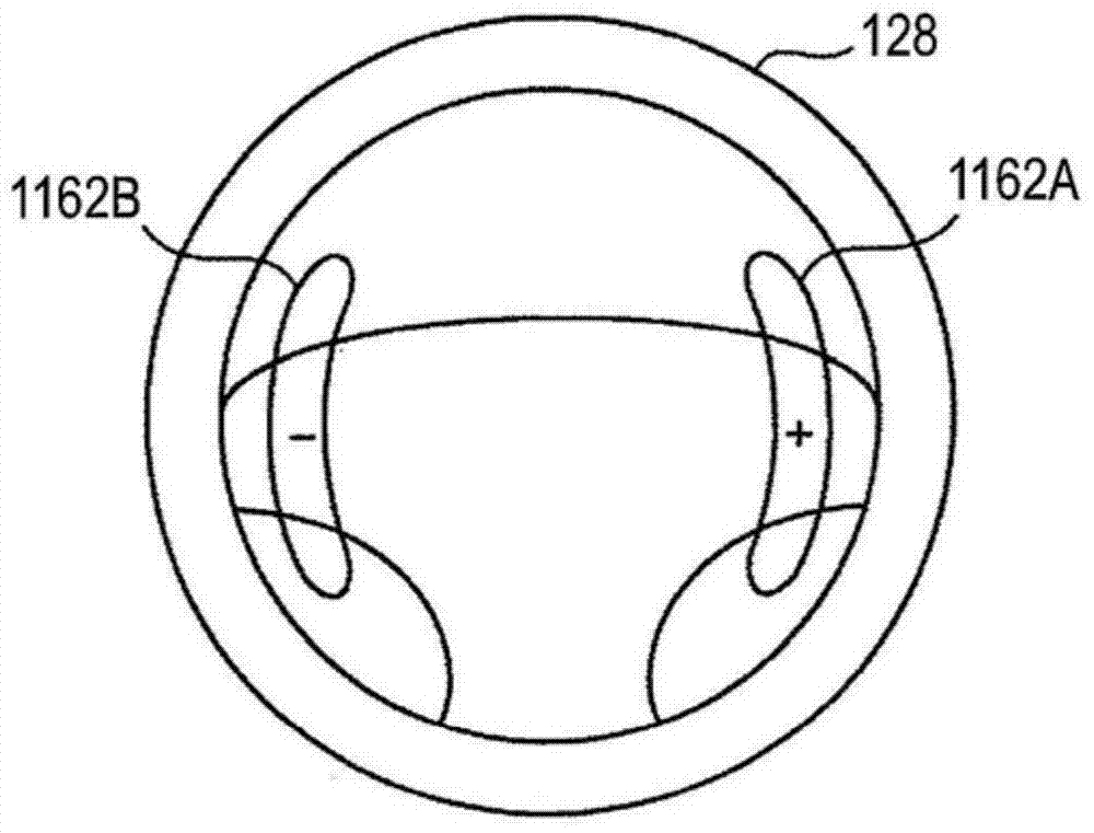
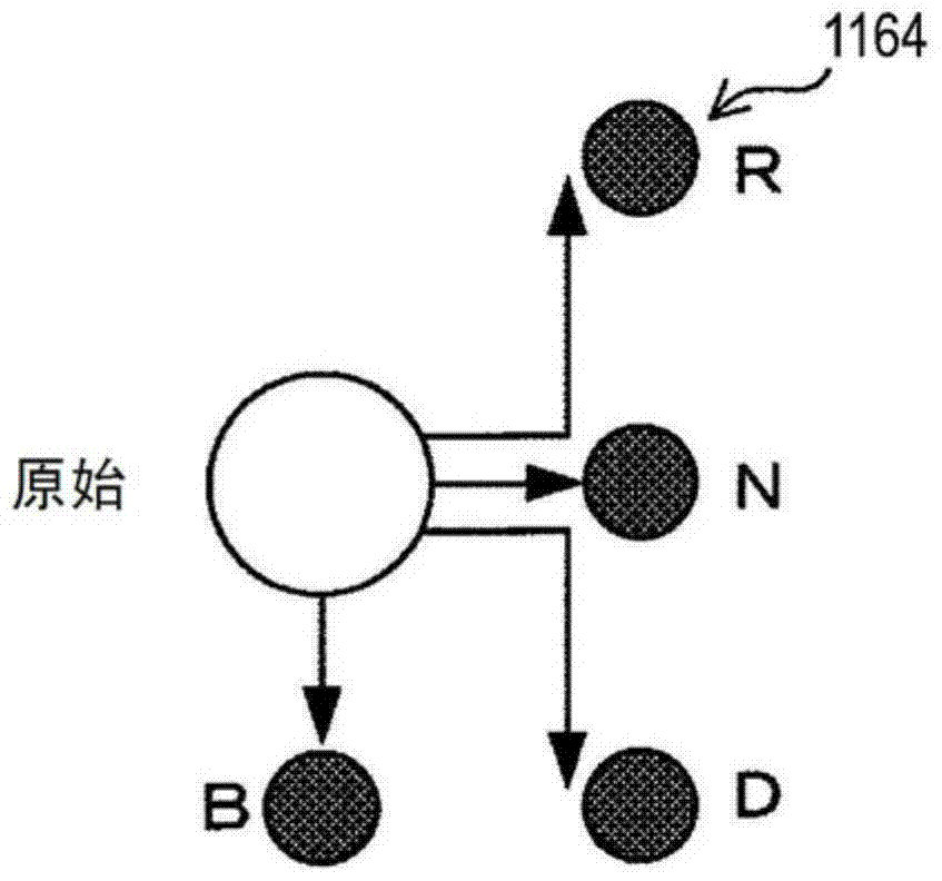
[0029] The hybrid vehicle 20 includes an engine 102, a power generating motor generator 104, a running motor generator 106, a battery (battery) 108, an inverter 110, a clutch 112, driving wheels 114, an operation unit 116 (gate switch (first operation unit) ) 1162, shift lever (second operating unit) 1164), vehicle speed sensor (vehicle speed detection unit) 118, accelerator pedal sensor 120, engine RPM sensor 122, state of charge detection circuit 124, temperature sensor 126, and vehicle ECU 130.

[0030] The engine 102 is an internal combustion engine such as a gasoline engine or a...


PUM


Abstract

A regenerative control device for a hybrid vehicle includes a regenerative braking force control unit that, when it is determined that it is necessary to limit charging of a battery, prohibits or limits execution of a first regenerative braking to utilize the power generated by walking during deceleration. The electric power generated by the regenerative power generation of the motor generator is used to charge the battery. In the case where the execution of the first regenerative braking is prohibited or limited, when the operation unit is set to the regeneration level in the increasing direction, the regenerative braking force control unit makes the power generated by the regenerative power generation The second regenerative braking in which the motor generator rotates to transmit the rotational driving force to the engine is performed, and when the operation unit is set to the regeneration level in the decreasing direction, the second regenerative braking is stopped.

Description

technical field [0001] The present invention relates to a regeneration control device for a hybrid vehicle. Background technique [0002] Among the hybrid vehicles equipped with an engine and a traveling motor as a driving source of the vehicle, there is a vehicle in which a traveling motor generator with a power generation function added to the traveling motor is used, and the motor generator for generating power is connected with the The traveling motor generator is separately coupled to the engine, so that the driving force of the engine can be connected to and disconnected from the power transmission path. In other words, this is a series-parallel hybrid vehicle in which the engine and the traveling motor generator separately perform generation and power generation of driving force. [0003] In the hybrid vehicle as described above, by using both the engine and the traveling motor generator, not only the power performance of the vehicle is improved but also the energy e...

Claims


Application Information

Patent Timeline
Patent Type & Authority Patents(China)
IPC IPC(8): B60L7/18H02J7/00B60L50/15B60L50/16
CPCB60K6/442B60K6/46B60W50/085B60L7/18B60L15/2009B60W10/08B60W20/00B60W2050/0073B60W2510/10B60W2510/244B60W2710/086B60L2240/12B60L2250/12B60L2270/145B60L50/61B60L50/51B60L58/13B60W30/18127B60W10/18B60L58/15Y02T10/72Y02T10/62Y02T10/64Y02T10/70Y02T10/7072
Inventor 池田谷文一上田克则本多谦太郎平野重利平尾忠义小熊孝弘佐藤琢矢
Owner MITSUBISHI MOTORS CORP
Features
  • R&D
  • Intellectual Property
  • Life Sciences
  • Materials
  • Tech Scout
  • Unparalleled Data Quality
  • Higher Quality Content
  • 60% Fewer Hallucinations
Learn More