Limiting thimble assembly and floor fan

A limit sleeve and assembly technology, which is applied to pump elements, connecting members, components of a pumping device for elastic fluid, etc., can solve problems such as cumbersome assembly of limit sleeve assemblies.

Active Publication Date: 2016-03-09
格力大松(宿迁)生活电器有限公司 +1
View PDF9 Cites 0 Cited by
  • Summary
  • Abstract
  • Description
  • Claims
  • Application Information

AI Technical Summary

Problems solved by technology

[0005] The main purpose of the present invention is to provide a limit sleeve assembly and a flo

Method used


Image

  • Limiting thimble assembly and floor fan
  • Limiting thimble assembly and floor fan
  • Limiting thimble assembly and floor fan

Examples


Embodiment Construction

[0025] It should be noted that, in the case of no conflict, the embodiments of the present invention and the features in the embodiments can be combined with each other. The present invention will be described in detail below with reference to the accompanying drawings and examples.

[0026] In order to enable those skilled in the art to better understand the solutions of the present invention, the following will clearly and completely describe the technical solutions in the embodiments of the present invention in conjunction with the drawings in the embodiments of the present invention. Obviously, the described embodiments are only It is an embodiment of a part of the present invention, but not all embodiments. Based on the embodiments of the present invention, all other embodiments obtained by persons of ordinary skill in the art without making creative efforts shall fall within the protection scope of the present invention.

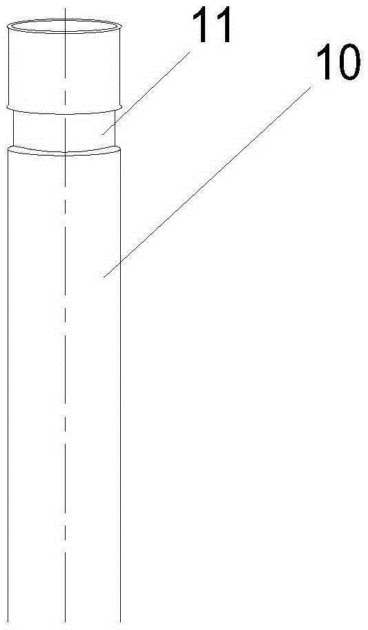
[0027] Figure 3 to Figure 5 The limit sleeve ...


PUM


Abstract

The invention provides a limiting thimble assembly and a floor fan. The limiting thimble assembly comprises an inner tube and a limiting sleeve arranged on the inner tube; a fixing part is disposed at the end of the inner tube; the limiting sleeve comprises an inner ring part and an outer ring part; a clamping part of which the shape is matched with that of the fixing part is disposed on the inner ring part; the outer ring part achieves limiting fit together with an outer tube and an outer tube inner joint. By means of the technical scheme, the problem of complicated assembling of limiting thimble assemblies in the prior art can be effectively solved.

Description

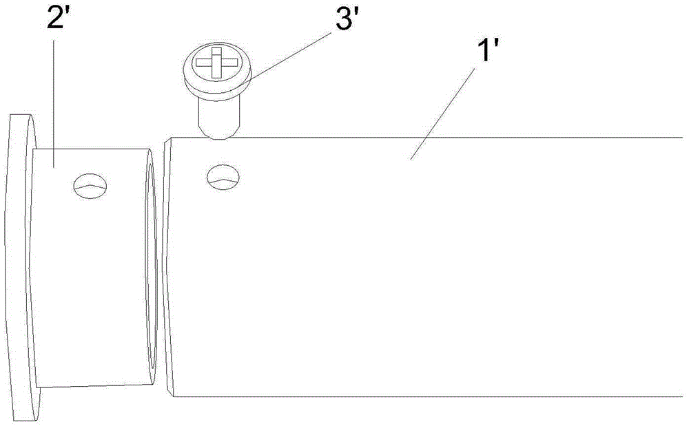
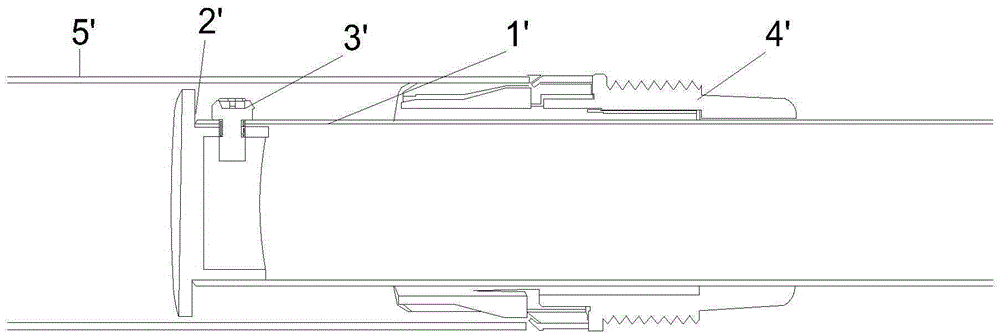
technical field [0001] The invention relates to the technical field of pipe fittings, in particular to a position-limiting sleeve assembly and a floor fan. Background technique [0002] Such as figure 1 Shown is the limiting bushing assembly in the prior art. When assembling the limit sleeve 2' tube assembly, align the limit sleeve 2' with the pipe end of the inner tube 1', align the installation holes on the limit sleeve 2' with the installation holes on the inner tube 1', and then use The screw 3' fastens the limit sleeve 2' and the inner tube 1'. [0003] Such as figure 2 As shown, when in use, insert the above-mentioned inner tube 1' together with the limit sleeve 2' into the outer tube 5', and then use the inner connection 4' of the outer tube to realize sealing, and the inner tube 1' can move relative to the outer tube 5' without leaving. [0004] It can be seen that in the process of installing the limit sleeve 2' on the inner tube 1', it is necessary to align t...

Claims


Application Information

Patent Timeline
IPC IPC(8): F16B7/10F04D29/66
CPCF04D29/66F16B7/10
Inventor 严必照杨立平李曙光陈宇强黄少杰
Owner 格力大松(宿迁)生活电器有限公司
Why Eureka
Try Eureka