
A thermal radiation shield for a frozen target

A thermal radiation shielding and freezing target technology, applied in the field of inertial confinement fusion, can solve problems such as inability to effectively protect the freezing target, achieve high engineering application value, good sealing effect, and improve the effect of cooling conduction

Active Publication Date: 2018-01-30
HARBIN INST OF TECH
View PDF6 Cites 0 Cited by
  • Summary
  • Abstract
  • Description
  • Claims
  • Application Information

AI Technical Summary

Problems solved by technology

[0003] In order to solve the problem that the frozen target cannot be effectively protected and its temperature constant and characterized before shooting, the present invention further proposes a thermal radiation shielding cover for the frozen target

Method used


Image

  • A thermal radiation shield for a frozen target
  • A thermal radiation shield for a frozen target

Examples


specific Embodiment approach 1

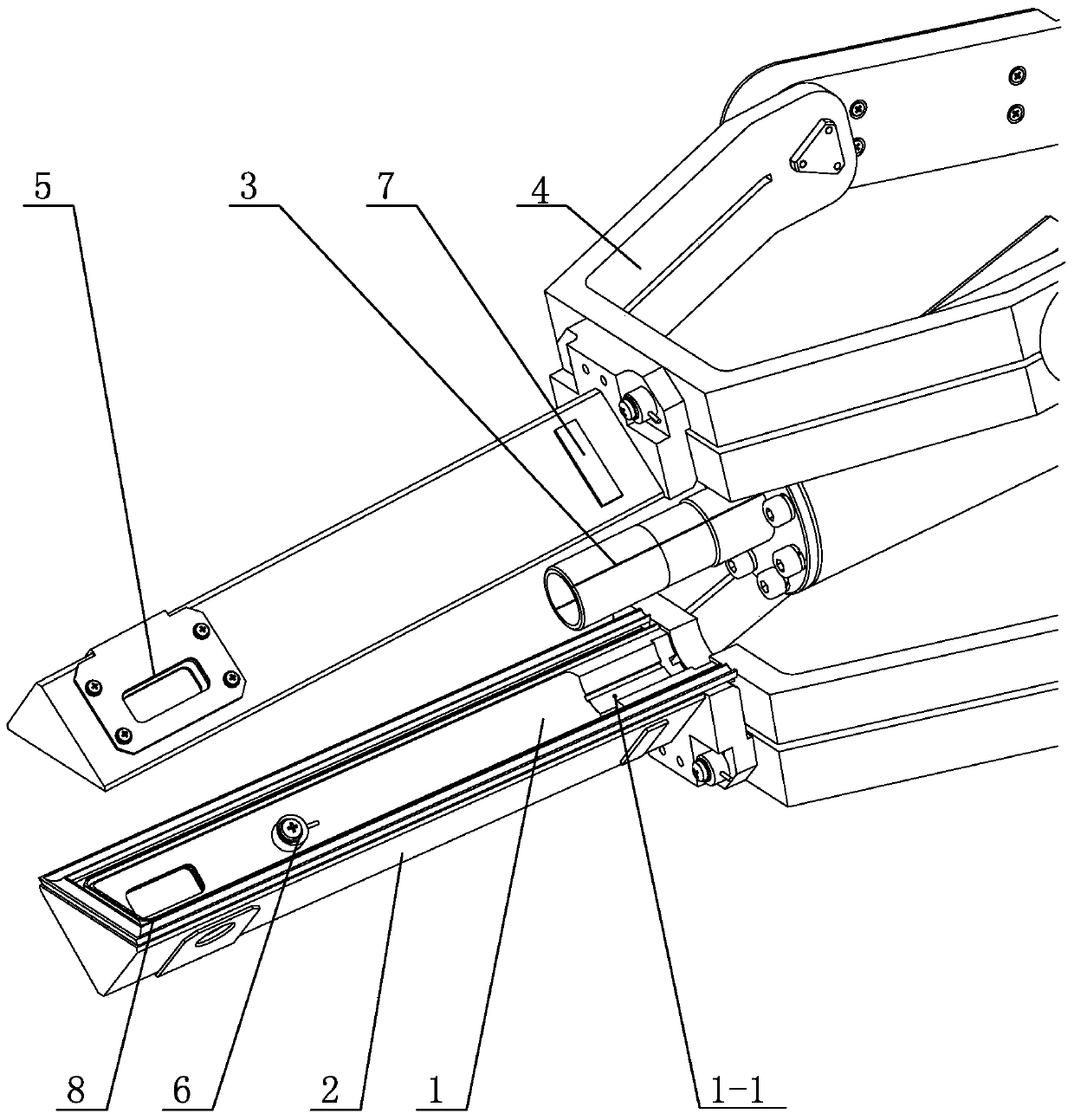
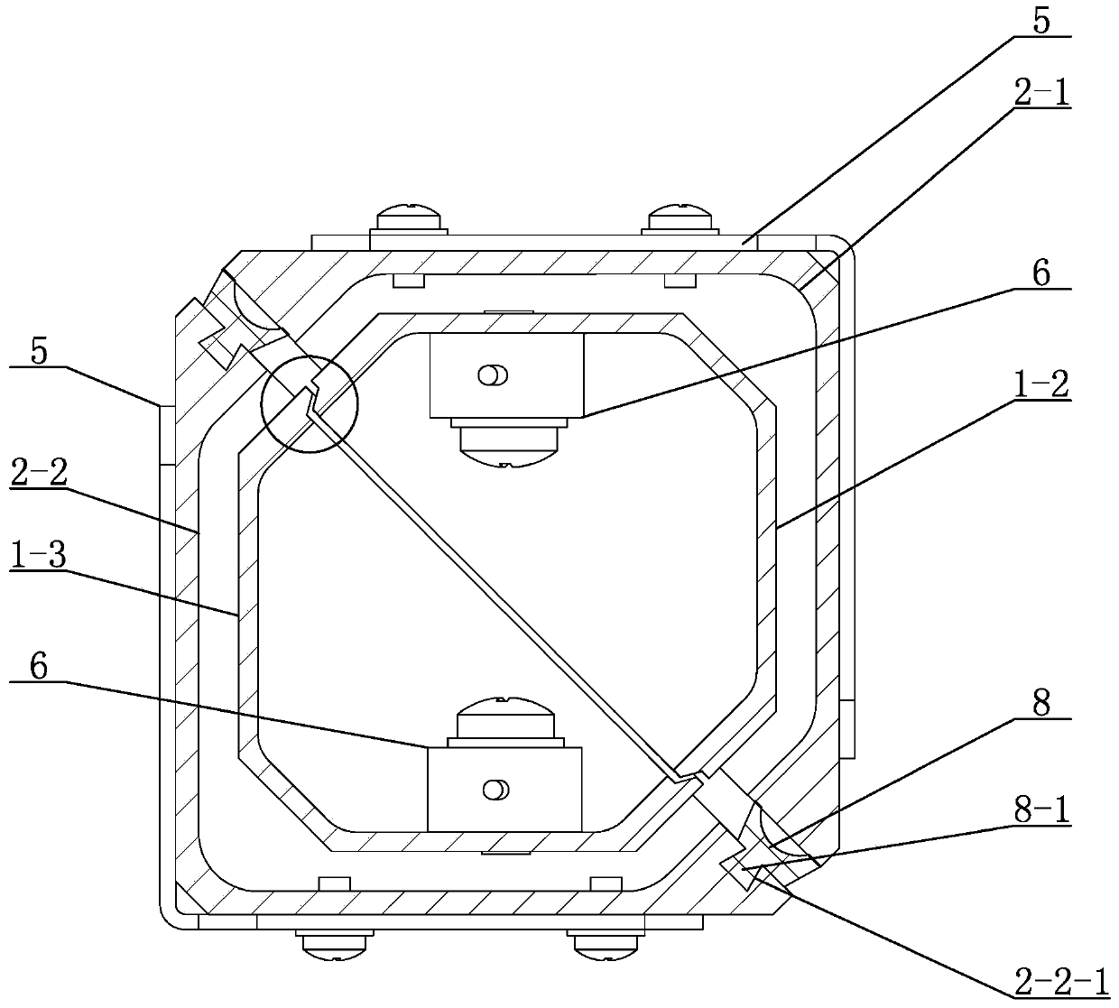
[0009] Specific implementation mode one: combine figure 1 and figure 2 Describe this embodiment, a thermal radiation shielding cover for a frozen target in this embodiment includes an inner shield 1, an outer shield 2, a low-temperature screen 3, an insulating arm 4, a sealing strip 8, and two aiming targets and a characterization window 5 , the inner shield 1 is arranged in the outer shield 2, the inner shield 1 and the outer shield 2 form a shield body, the low temperature shield 3 is arranged in the shield body, and when the shield body is combined, the low temperature shield 3 and the inner shield The cold guide part 1-1 of the shielding cover 1 is connected, and the contact surface of the cold guide part 1-1 adopts the annular structure of the longitudinal groove. The shielding cover body is installed on the heat insulating arm 4, and the inner shielding cover 1 includes the upper inner half cover The body 1-2 and the lower inner half-cover 1-3, the upper inner half-cov...

specific Embodiment approach 2

[0016] Specific implementation mode two: combination figure 1 and figure 2 Illustrate this embodiment, the heat radiation shielding cover of a cryogenic target described in this embodiment also includes two temperature sensors 6, a temperature sensor 6 is arranged on the inner side wall of the upper inner half cover body 1-2, and the lower inner half cover body A temperature sensor 6 is provided on the inner wall of 1-3. Other components and connections are the same as those in the first embodiment.

specific Embodiment approach 3

[0017] Specific implementation mode three: combination figure 1 and figure 2 Describe this embodiment, the heat radiation shielding cover for a frozen target described in this embodiment also includes two heating blocks 7, one heating block 7 is arranged on the outer side wall of the other end of the upper outer half cover 2-1, and the lower outer half A heating block 7 is provided on the outer wall of the other end of the cover body 2-2. Other components and connections are the same as those in the first embodiment.


PUM


Abstract

The invention relates to a shielding case, in particular to a heat radiation shielding case of a refrigeration target. Problems of failures to effectively protect a refrigeration target and maintain constant temperature and representation in the current refrigeration target shooting are solved. The shielding case comprises an inner shielding case, an outer shielding case, a low temperature screen, a heat insulation arm, a sealing rubber strip, two target aiming and representation windows. The inner shielding case is arranged in the outer shielding case. The inner shielding case and the outer shielding case form a shielding case body. The low temperature screen is arranged in the shielding case body. When the shielding case body is closed, the low temperature screen is connected with a cold guiding part of the inner shielding case. The contact face of the cold guiding part is of an annular vertical groove structure. The invention belongs to the field of inertial confinement fusion.

Description

technical field [0001] The invention relates to a shielding cover, in particular to a thermal radiation shielding cover of a frozen target, belonging to the field of inertial confinement fusion. Background technique [0002] Inertial confinement fusion is an effective way to realize controllable thermonuclear fusion, an effective way to solve the energy problems faced by human beings, and it is also the strategic commanding height of science and technology that developed countries are competing to occupy. And technology can create the extreme physical conditions required for some scientific experiments, and also has important applications in the defense science and technology industry. Compared with conventional targets, the number of neutrons produced by fusion of frozen targets has increased significantly, and it is the most promising target type to achieve fusion first. Frozen targets need to maintain ultra-low temperature below 18K to ensure that the target is in a froz...

Claims


Application Information

Patent Timeline
Patent Type & Authority Patents(China)
IPC IPC(8): G21B1/13G21F3/00
CPCG21B1/13G21F3/00Y02E30/10
Inventor 刘彦武王辉
Owner HARBIN INST OF TECH
Learn More